Device and method for locating partial discharges

a technology of partial discharge and device, applied in the direction of fault location, testing circuit, instruments, etc., can solve the problems of not being able to detect, the method is not very reliable for long cables, and the partial discharge is substantially limited, so as to achieve reliable and robust results

Active Publication Date: 2014-06-24
I S A ALTANOVA GRP SRL
View PDF15 Cites 0 Cited by
  • Summary
  • Abstract
  • Description
  • Claims
  • Application Information

AI Technical Summary

Benefits of technology

[0039]More specifically, the aim of this invention is to provide a device and a method for locating in a particularly accurate and precise manner partial discharges occurring at a discharge site in an electric apparatus with elongate geometry and generating corresponding electric pulses propagating in opposite directions axially along the apparatus from the discharge site.
[0042]Another aim of the invention is to provide a device and a method for locating partial discharges that are particularly reliable and robust in identifying a pair of homologous pulses used for locating.

Problems solved by technology

By their very nature, therefore, partial discharges are substantially limited in extent to a defect in the insulating system.
This method is not very reliable for long cables since the signals travelling the cable are attenuated to such an extent that there is the risk of not being able to detect them at all at the detecting station.
This method is more accurate than the reflectometric method but poses some problems.
A first problem is that of identifying a pair of homologous pulses, that is to say, pulses assignable to the same partial discharge and propagating in opposite directions.
These systems have two drawbacks, however.
A first drawback is due to the difficulty of reliably identifying the partial discharges to be examined.
That is to say, the fact that two signals are detected by respective sensors in a sufficiently short interval of time (compatibly with the estimated speed of pulse propagation in the apparatus and the distance between the sensors) does not guarantee that those signals are from partial discharges, and in particular from the same partial discharge.
In fact, numerous signals may be coupled to the sensors other than the target signals corresponding to the partial discharges to be identified; these unwanted signals may consist of background noise or disturbances of another nature, or even other partial discharges (occurring at another discharge site or outside the cable).
These systems do not, however, make it possible to determine whether the signals detected are due to the same partial discharge activity.
Indeed, it is impossible to provide sensors optimized for each and every circumstance and the filtering systems are often ineffective.
Also, since the frequency of the target discharge signals to be detected is not known beforehand, there is the risk of filtering out those very signals.
Lastly, when the signals generated by target partial discharge activities to be detected are accompanied by other signals generated by partial discharges to be ignored (for example because they are outside the cable), there is the risk that these signals cannot be selectively processed with filtering systems currently in use (consisting, for example, of analog passband filters).
This may lead to serious processing errors since the pulses, during their propagation in the apparatus, are deformed in proportion to the space travelled.
Also, there is a limit to the precision with which a time phase shift can be sensed by the instruments (even on the absurd assumption that the reference points for the pulses to be compared match perfectly).
In light of this, the prior art methods do not guarantee reliable results and are often ineffective.

Method used


Image

  • Device and method for locating partial discharges
  • Device and method for locating partial discharges
  • Device and method for locating partial discharges

Examples


Embodiment Construction

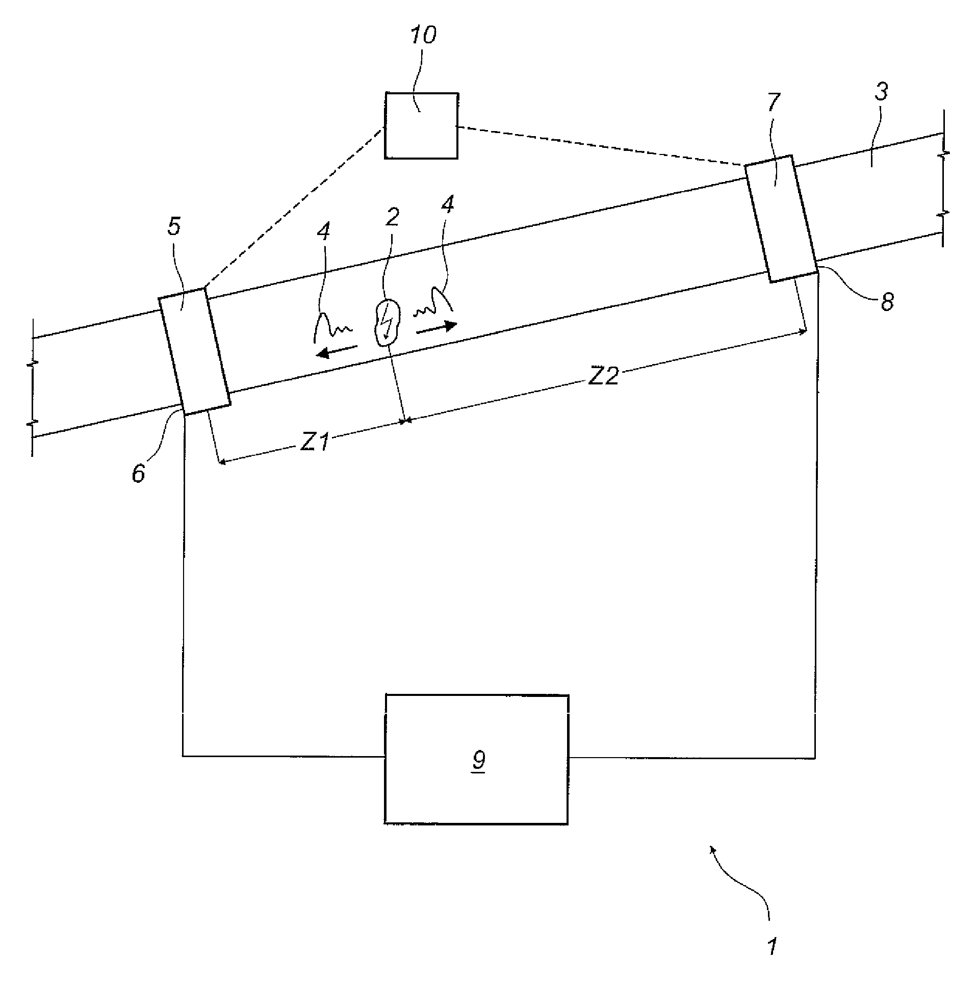
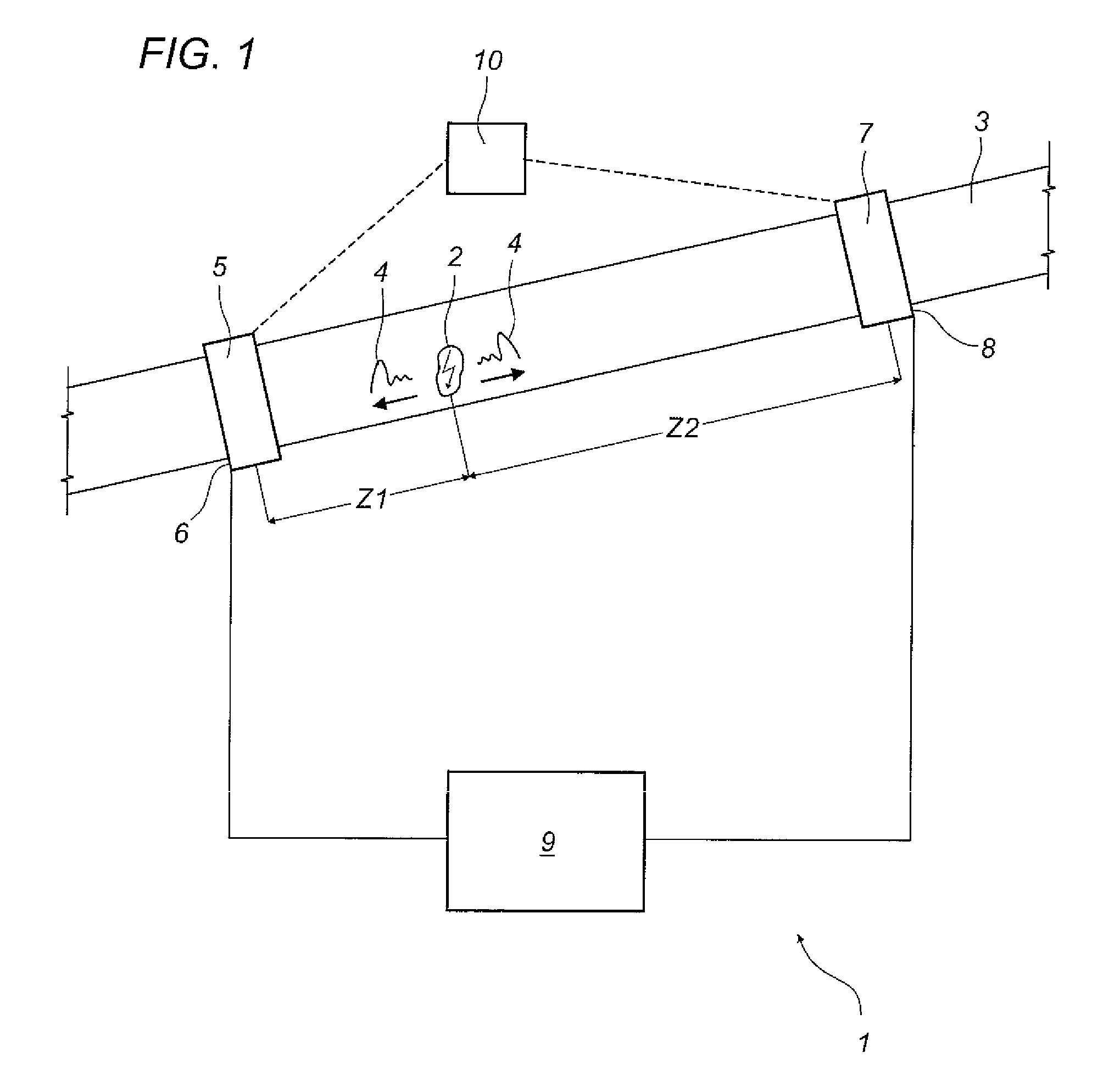
[0052]The numeral 1 in FIG. 1 denotes a device according to this invention.

[0053]The device 1 is a device used for locating partial discharges occurring at a discharge site 2 in an electric apparatus 3 with elongate geometry and generating corresponding electric pulses 4 propagating in opposite directions axially along the apparatus 3 from the discharge site 2.

[0054]The device 1 for locating partial discharge sites is applicable, for example, on medium and high voltage cables, autotransformers or GILs.

[0055]The device 1 comprises a first sensor 5 which can connect to the apparatus 3 (for example to the cable) at a first detecting station 6.

[0056]The device 1 also comprises a second sensor 7 which can connect to the apparatus 3 at a second detecting station 8.

[0057]The sensors 5 and 7 are configured to detect analog electric signals representative of the waveform of the discharge pulses 4.

[0058]The sensors 5, 7 consist, for example, of magnetic probes, inductive or capacitive probes,...


PUM


Abstract

A method for locating partial discharges occurring at a discharge site (2) in an electric apparatus (3) with elongate geometry and generating corresponding electric pulses (4) propagating in opposite directions along the apparatus (3) from the discharge site (2) comprises the steps of detecting (11) the electric pulses (4) picked up by a first and a second sensor (5, 7), operatively connected to the apparatus (3) and spaced out along it, and generating corresponding electric signals representative of the waveform of the pulses (4), selecting (12) at least one pair of signals, detected in the consecutive sensors (5, 7), and representative of a pair of homologous pulses (4), relating to the same partial discharge and propagating in opposite directions along the apparatus, deriving, for the signals of the selected pair of homologous pulses (4), at least one attenuation parameter, correlated with a quantity that is variable depending on the distance travelled by the pulses (4), calculating (13) the distance between the discharge site (2) and the sensors, based on processing the values of the attenuation parameter for the signals of the selected pair of homologous pulses (4).

Description

TECHNICAL FIELD[0001]This invention relates to a device and a method for locating partial discharges occurring at a discharge site in an electric apparatus with elongate geometry and generating corresponding electric pulses propagating in opposite directions along the apparatus from the discharge site.[0002]More generally, this invention relates to the technical field of diagnosing electrical systems (particularly high-voltage systems) by detecting / processing partial electrical discharges.BACKGROUND ART[0003]It should be noted that a partial discharge is an electric discharge limited to a portion of the insulation of an electrical system and does not therefore cause immediate failure of the system but its gradual degradation. By their very nature, therefore, partial discharges are substantially limited in extent to a defect in the insulating system.[0004]In light of this, diagnostic methods based on the detection and interpretation of partial discharges are among the most promising ...

Claims


Application Information

Patent Timeline
Patent Type & Authority Patents(United States)
IPC IPC(8): G01R31/00G01R31/08G01R31/28
CPCG01R31/08G01R31/088G01R31/1272G01R31/14
Inventor SERRA, STEFANOCAVALLINI, ANDREAMONTANARI, GIAN CARLOPASINI, GAETANO
Owner I S A ALTANOVA GRP SRL
Why Eureka
Try Eureka