Linear actuator

a linear actuator and actuator body technology, applied in the direction of gearing control, gearing elements, gearing, etc., can solve the problems of low efficiency and large building size, large overall size, and difficulty in fitting in small cylinders

Pending Publication Date: 2022-10-27
EXCESS ENG AS
View PDF4 Cites 1 Cited by
  • Summary
  • Abstract
  • Description
  • Claims
  • Application Information

AI Technical Summary

Benefits of technology

[0010]A primary object of this invention is to provide a compact device to efficient transform rotational movement in to linear (lateral) movement, and vice versa.
[0014]Another object of the invention is to provide an accurate and precise tool enable to perform at a controllable speed with high positioning accuracy.
[0024]EP2916042 Discloses an electric linear actuator which can reduce damage and wear of the housing and perform the anti-rotation of the nut with a simple structure to improve the reliability and manufacturing cost of the electric linear actuator. The drawback of this design is the dependency of the helical grooves on the screw shaft which tends to make the overall size large by using a driving screw shaft with proportionally same length as the stroke of the piston rod.

Problems solved by technology

Many systems have been patented and developed to compete with the hydraulic actuators, but low efficiency and large building size has prevented electric energy to become the preferred method.
The drawback of this type of design having an external recirculation system is the overall size tends to be large and difficult to fit in small cylinders.
The drawback of this design is the dependency of a thread system on the center screw (lateral moving shaft) making the system overall size large if the lateral moving shaft needs to be sealed off due to ambient pressure or dusty environment.
The drawback is the dependency of thread system on the lateral moving screw.
Thus, making the design large in size and difficult to fit into a compact linear actuator.
The drawback of this design is the dependency of the helical grooves on the screw shaft which tends to make the overall size large by using a driving screw shaft with proportionally same length as the stroke of the piston rod.
The drawback of this design is that the balls disposed in the ball circulation grooves 33 and 34 can be subject to neither a radial load nor an axial load.

Method used


Image

  • Linear actuator
  • Linear actuator
  • Linear actuator

Examples


Embodiment Construction

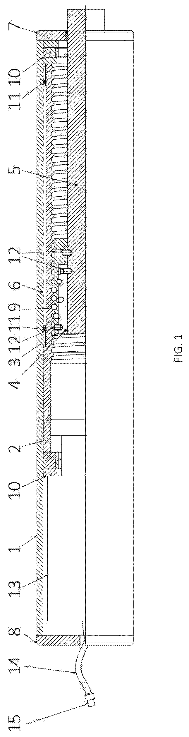
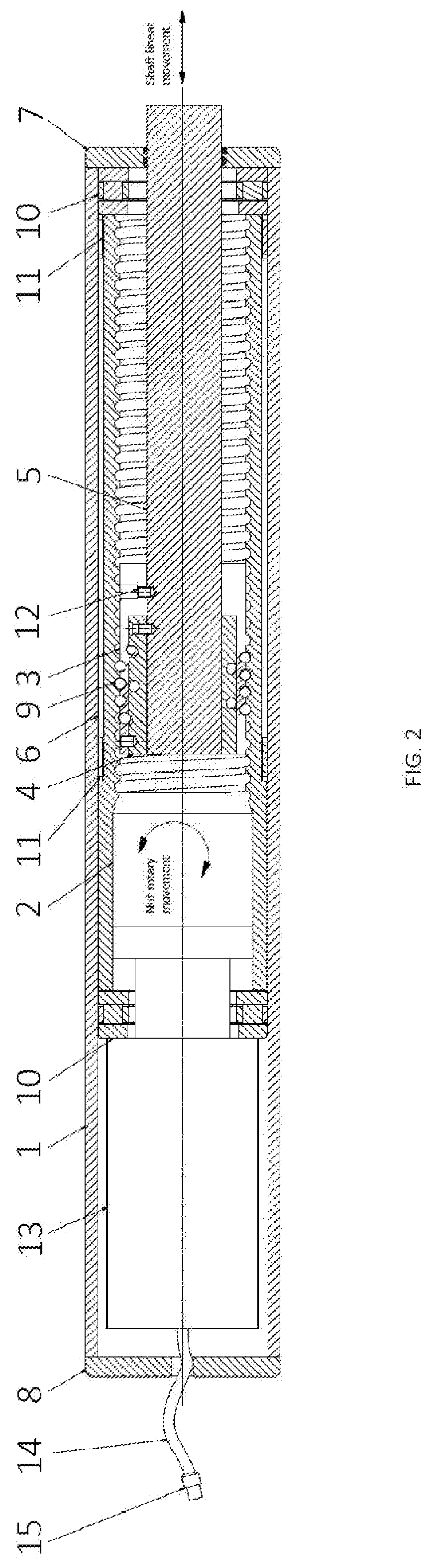
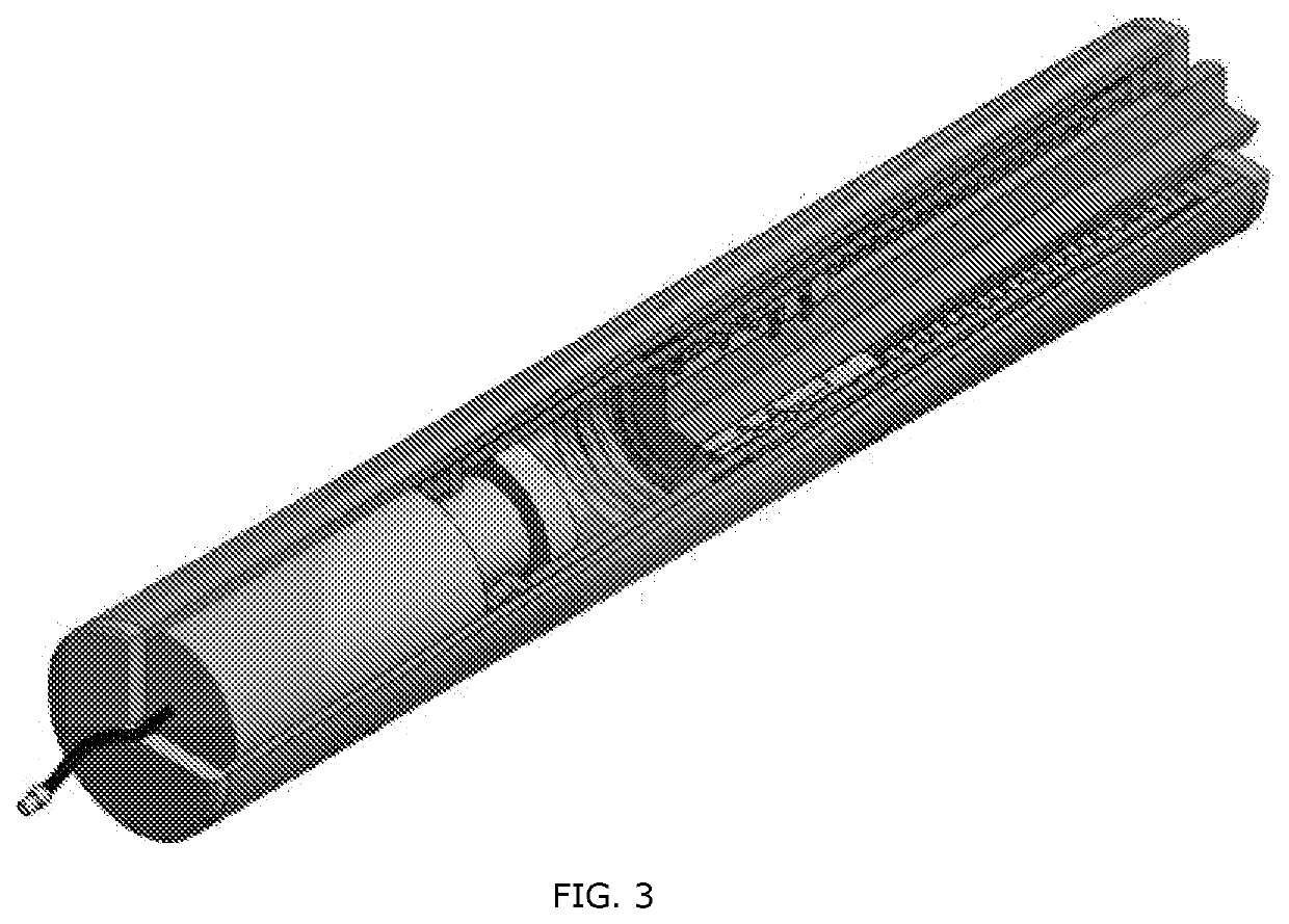
[0026]Characteristics and advantages of the present disclosure and additional features and benefits will be readily apparent to those skilled in the art upon consideration of the following detailed description of exemplary embodiments of the present disclosure and referring to the accompanying figures. It should be understood that the description herein and appended drawings, being of example embodiments, are not intended to limit the claims of this patent application, any patent granted hereon or any patent or patent application claiming priority hereto. On the contrary, the intention is to cover all modifications, equivalents and alternatives falling within the spirit and scope of the claims. Many changes may be made to the embodiments and details disclosed herein without departing from such spirit and scope. The objects, advantages, and features of the invention will become more apparent by reference to the drawings which are appended hereto and wherein like numerals indicate lik...


PUM


Abstract

This invention generally concerns the field of linear actuator in a cylindric housing. More particular, the present disclosure relates to a ball screw driven linear actuator for converting rotational movement into linear movement, and vice versa. The present disclosure has use to applications requiring high performance, high force and speed. This invention is performing both at surface and subsea

Description

BACKGROUND ART[0001]Industry today has high focus on efficiency, environment and digitalization to perform operations at land, at sea and subsea. One of the focus over the past years is to use efficient electric power to perform the tasks as to replace the more inefficient hydraulic systems. Many tasks are already performed by electric motors today. One main advantage of the hydraulic systems is that in a compact system it is possible to transfer high force by use of hydraulic cylinders and actuators. Many systems have been patented and developed to compete with the hydraulic actuators, but low efficiency and large building size has prevented electric energy to become the preferred method. The present invention relates to an improved and more efficient system of transferring the rotational torque into linear force. The present invention consisting of a compact ball screw linear actuator system with recirculation of bearing balls and provides the required efficiency and accuracy dema...

Claims


Application Information

Patent Timeline
Patent Type & Authority Applications(United States)
IPC IPC(8): F16H25/22F16H25/20
CPCF16H25/2228F16H25/2015F16H2025/2075F16H61/28F16H57/02F16H2061/2884
Inventor KALVATN, OVEMOKRZYCKI, ADAMELLINGSEN, JAN
Owner EXCESS ENG AS
Why Eureka
Try Eureka