Clip advancer with lockout mechanism

a technology of lockout mechanism and advancer, which is applied in the field of surgical devices, can solve the problems of wasting surgeons valuable time in repeating at least a portion of the closing procedure, general no indication of when the clip applier is applied, and affecting the safety of patients

Active Publication Date: 2011-04-14
CILAG GMBH INT
View PDF100 Cites 109 Cited by
  • Summary
  • Abstract
  • Description
  • Claims
  • Application Information

AI Technical Summary

Benefits of technology

[0007]In some embodiments, movement of the trigger from an open position to a closed position can be effective to move the advancer assembly from the proximal position to the distal position. The surgical access device can also include a clip track disposed within the elongate shaft and having a plurality of clips seated therein, and the feeder shoe can be slidably disposed within the clip track to distally advance the plurality of clips through the clip track. In one embodiment, the advancer assembly can include a recess formed therein that is configured to be engaged by a tang on the feeder shoe to prevent the advancer assembly from moving to the proximal position after the advancer assembly has moved a proximal-most clip into the opposed jaws. The tang on the feeder shoe can be configured to move distally with the feeder shoe as the feeder shoe advances the plurality of clips through the clip track.
[0010]In some embodiments, the surgical clip applier can further include a pawl and ratchet mechanism disposed within the handle housing and operatively associated with the trigger. The pawl and ratchet mechanism can have an engaged configuration in which the pawl and ratchet mechanism controls movement of the trigger and a disengaged configuration in which the trigger is movable independently of the pawl and ratchet mechanism. The lockout mechanism can be configured to lock the pawl and ratchet mechanism in an engaged configuration after the clip advancing assembly has advanced a proximal-most clip into the opposed jaws to thereby lock the trigger in an actuated position.
[0013]In another aspect, methods for advancing surgical clips are provided and can include moving a trigger from an open-most position to a closed-most position to correspondingly advance a proximal-most clip of a plurality of clips into opposed jaws of a clip applier. The method can further include releasing the trigger such that the trigger is locked in an actuated position between the open-most and closed-most positions to prevent the trigger from being moved to the open-most position. A tang formed on a feeder shoe can be engaged by a recess formed in an advancer assembly to lock the trigger. In some embodiments, moving the trigger from the open-most position to the closed-most position can move the advancer assembly distally over the feeder shoe to advance the proximal-most clip into the opposed jaws of the clip applier. Furthermore, releasing the trigger can move the advancer assembly proximally over the feeder shoe until the recess in the advancer assembly engages the tang on the feeder shoe. The method can also include releasing the proximal-most clip from the opposed jaws of the clip applier before the trigger is locked in an actuated position between the open-most and closed-most positions to prevent the trigger from being moved to the open-most position.

Problems solved by technology

One problem associated with advancer mechanisms is that there is generally no indication of when the clip applier is out of clips.
Such a mistake could be dangerous to the patient, and at a minimum, could cost the surgeon valuable time in having to repeat at least a portion of the closing procedure.

Method used


Image

  • Clip advancer with lockout mechanism
  • Clip advancer with lockout mechanism
  • Clip advancer with lockout mechanism

Examples


Embodiment Construction

[0103]The present invention generally provides a surgical clip applier and methods for using a surgical clip applier to apply surgical clips to a vessel, duct, shunt, etc., during a surgical procedure. An exemplary surgical clip applier can include a variety of features to facilitate application of a surgical clip, as described herein and illustrated in the drawings. However, a person skilled in the art will appreciate that the surgical clip applier can include only some of these features and / or it can include a variety of other features known in the art. The surgical clip applier described herein is merely intended to represent certain exemplary embodiments.

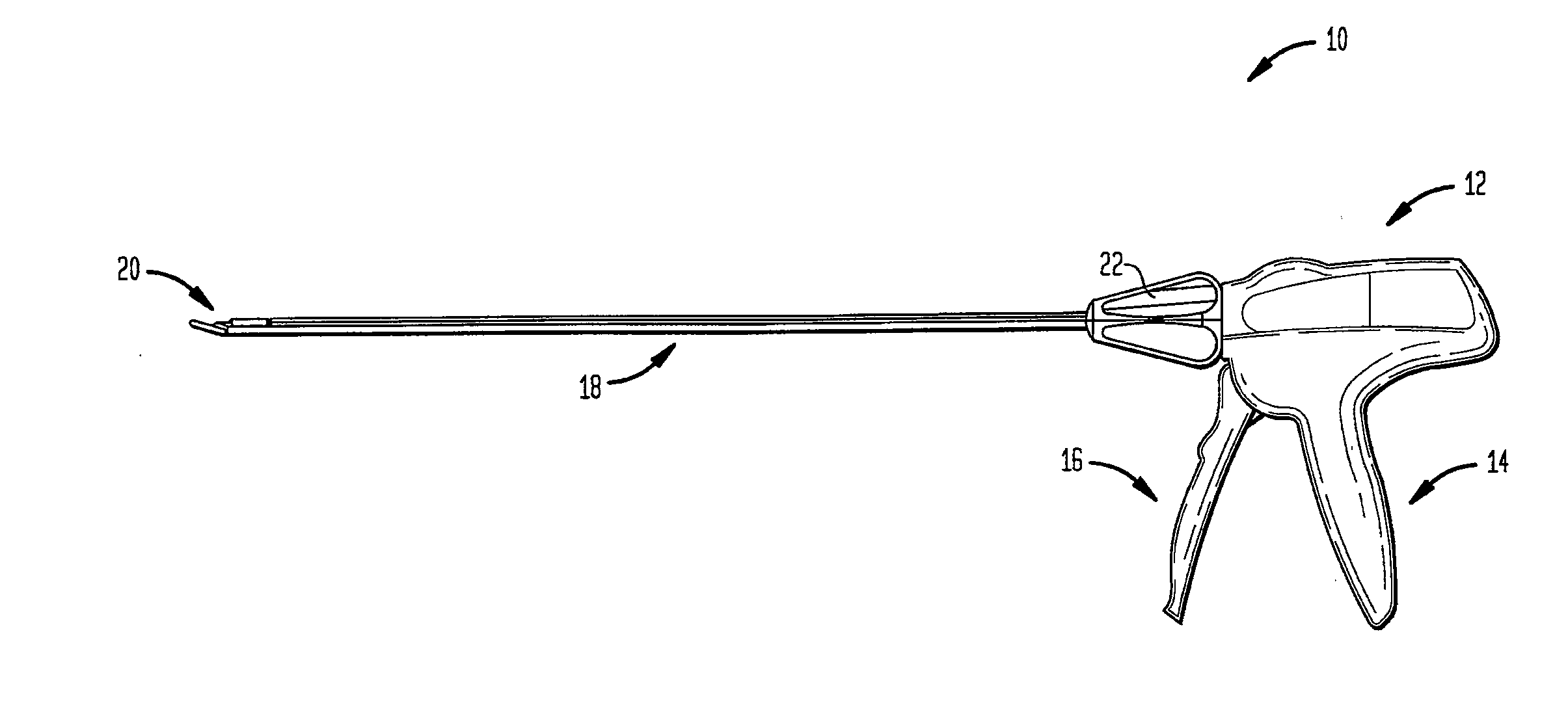
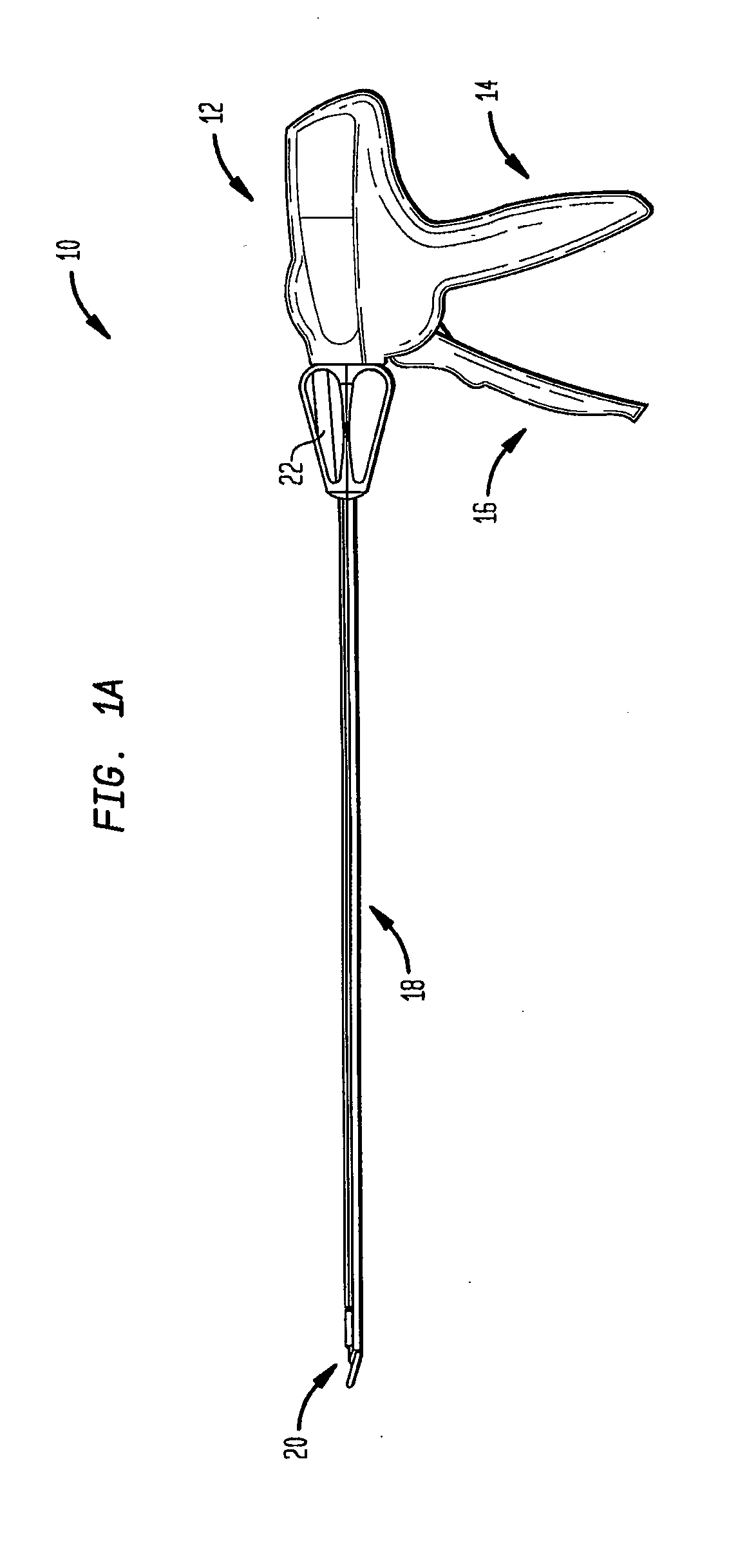
[0104]FIG. 1A illustrates one exemplary surgical clip applier 10. As shown, the clip applier 10 generally includes a housing 12 having a stationary handle 14 and a movable handle or trigger 16 that is pivotally coupled to the housing 12. An elongate shaft 18 extends from the housing 12 and it includes a pair of opposed jaws 20 f...


PUM


Abstract

A surgical clip applier and methods for applying surgical clips to a vessel, duct, shunt, etc., during a surgical procedure are provided. In one embodiment, a surgical clip applier is provided and can include a housing having a trigger movably coupled thereto and an elongate shaft extending therefrom with opposed jaws formed on a distal end thereof. The clip applier can include an advancer assembly disposed within the elongate shaft and configured to advance one of a plurality of clips disposed within the elongate shaft into the opposed jaws. A feeder shoe can be disposed within the elongate shaft and can be configured to engage and prevent the advancer assembly from moving to a proximal position after the advancer assembly has moved to a distal position to advance a proximal-most clip into the opposed jaws. This can indicate to a user that a clip supply of the surgical clip applier is depleted.

Description

CROSS-REFERENCE TO RELATED APPLICATIONS[0001]The present application is a continuation-in-part of U.S. application Ser. No. 12 / 576,736 filed Oct. 9, 2009 and entitled “Improved Clip Advancer” which is hereby incorporated by reference in its entirety.FIELD OF THE INVENTION[0002]The present invention relates broadly to surgical devices, and in particular to methods and devices for applying surgical clips to ducts, vessels, shunts, etc.BACKGROUND OF THE INVENTION[0003]Surgical clip appliers are commonly used for ligating blood vessels, ducts, shunts, or a portion of body tissue during surgery. Most clip appliers typically have a handle with an elongate shaft having a pair of movable opposed jaws formed on an end thereof for holding and forming a ligation clip therebetween. The jaws are positioned around the vessel or duct, and the clip is crushed or formed on the vessel by the closing of the jaws.[0004]Clip appliers that are configured to deliver multiple clips typically include an adv...

Claims


Application Information

Patent Timeline
Patent Type & Authority Applications(United States)
IPC IPC(8): A61B17/10
CPCA61B17/2909A61B17/1285A61B2019/4836A61B2090/0807A61B2017/00407
Inventor NGUYEN, ANTHONY T.HERRERA-DAVIS, DENZEL Z.
Owner CILAG GMBH INT
Why Eureka
Try Eureka