Flexible neural probe for magnetic insertion

a neural probe and flexible technology, applied in the field of flexible electrodes used with neural tissues, can solve the problems of still limiting the functional lifespan of chronically implanted electrodes, sacrificing flexibility, and compromising the stiffness of silicon microelectrodes, so as to prevent buckling, discriminate single unit activity, and limited spatial resolution

Active Publication Date: 2014-06-24
PURDUE RES FOUND INC
View PDF4 Cites 1 Cited by
  • Summary
  • Abstract
  • Description
  • Claims
  • Application Information

AI Technical Summary

Benefits of technology

[0009]The present invention overcomes or ameliorates at least one of the prior art disadvantages discussed above or provides a useful alternative thereto by providing a novel system for implanting a flexible neural probe by using an induced magnetic field to accelerate a magnetic tip tethered to a flexible length of conductive wire into neural tissue. In accordance with certain aspects of the present invention, the tether is pulled by the magnetic tip and held in tension during insertion to prevent buckling. Preliminary in vivo results have demonstrated that even though the current dimensions of the recording tip have somewhat limited spatial resolution, these inventive probes can be used to discriminate single unit activity. As such, it is envisioned that further refinement of the inventive embodiments will make it possible to safely implant soft, flexible probes in an accurate and precise manner into deep brain structures for chronic neural recording. Moreover, the concurrent use of flexible electrode materials is envisioned to reduce micromotion-induced stress, thereby lessening the severity of chronic glial scarring.

Problems solved by technology

However, while great strides have been made in neural interfacial technologies, signal degradation due glial scar formation still limits the functional lifespan of chronically implanted electrodes.
One of the fundamental problems with current electrodes is the dichotomy between the material properties needed for implantation and the properties required to minimize long term neural trauma.
Silicon microelectrodes possess the required stiffness but sacrifice flexibility.
However, such measures fail to address the severe mechanical mismatch between neural tissue and the probes themselves.
Implantation using traditional techniques is difficult due to their increased flexibility.
Despite using soft materials, the majority of such devices must compromise flexibly for the ability to exert enough compressive force for implantation.

Method used


Image

  • Flexible neural probe for magnetic insertion
  • Flexible neural probe for magnetic insertion
  • Flexible neural probe for magnetic insertion

Examples


Embodiment Construction

[0027]The embodiments of the present invention described below are not intended to be exhaustive or to limit the invention to the precise forms disclosed in the following detailed description. Rather, the embodiments are chosen and described so that others skilled in the art may appreciate and understand the principles and practices of the present invention.

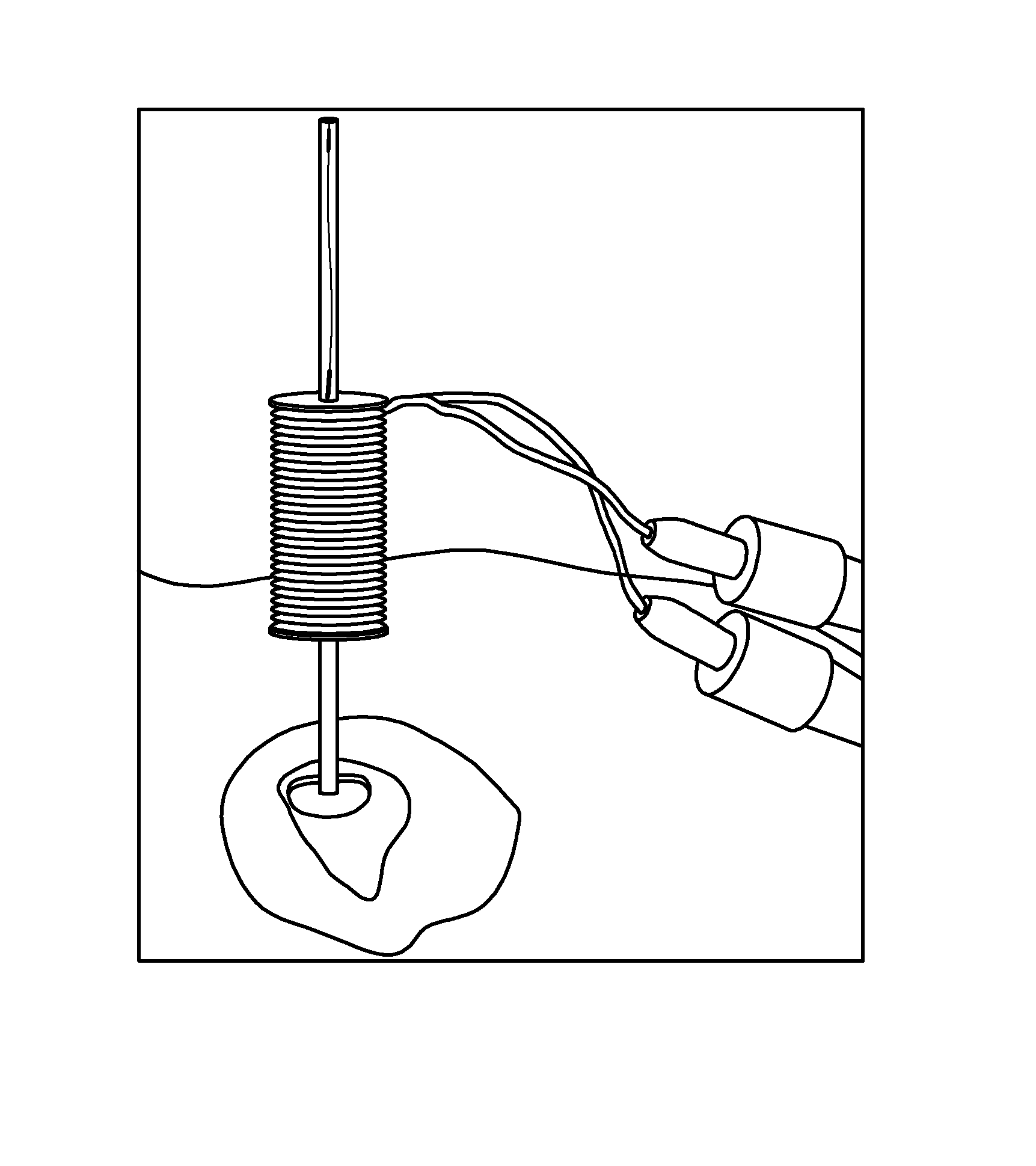
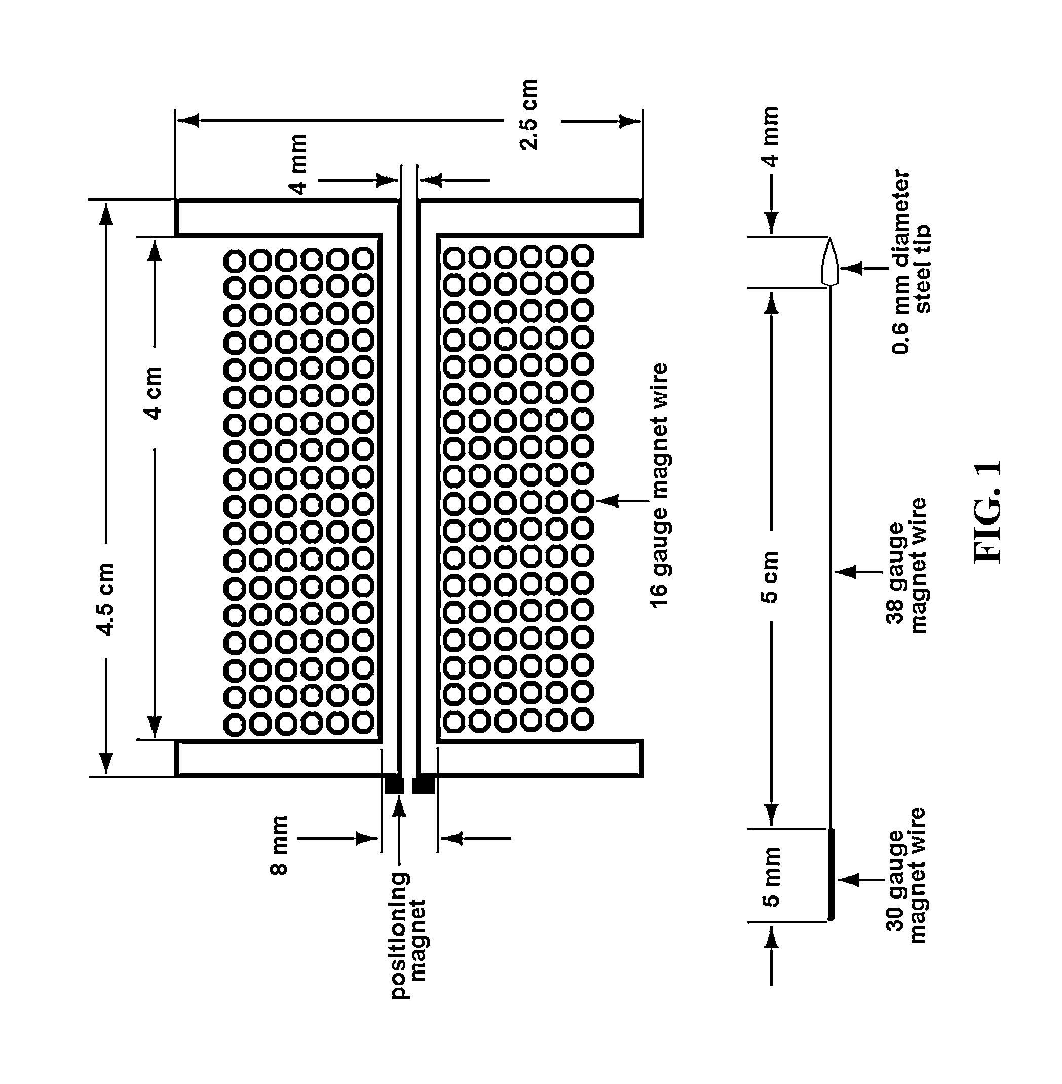
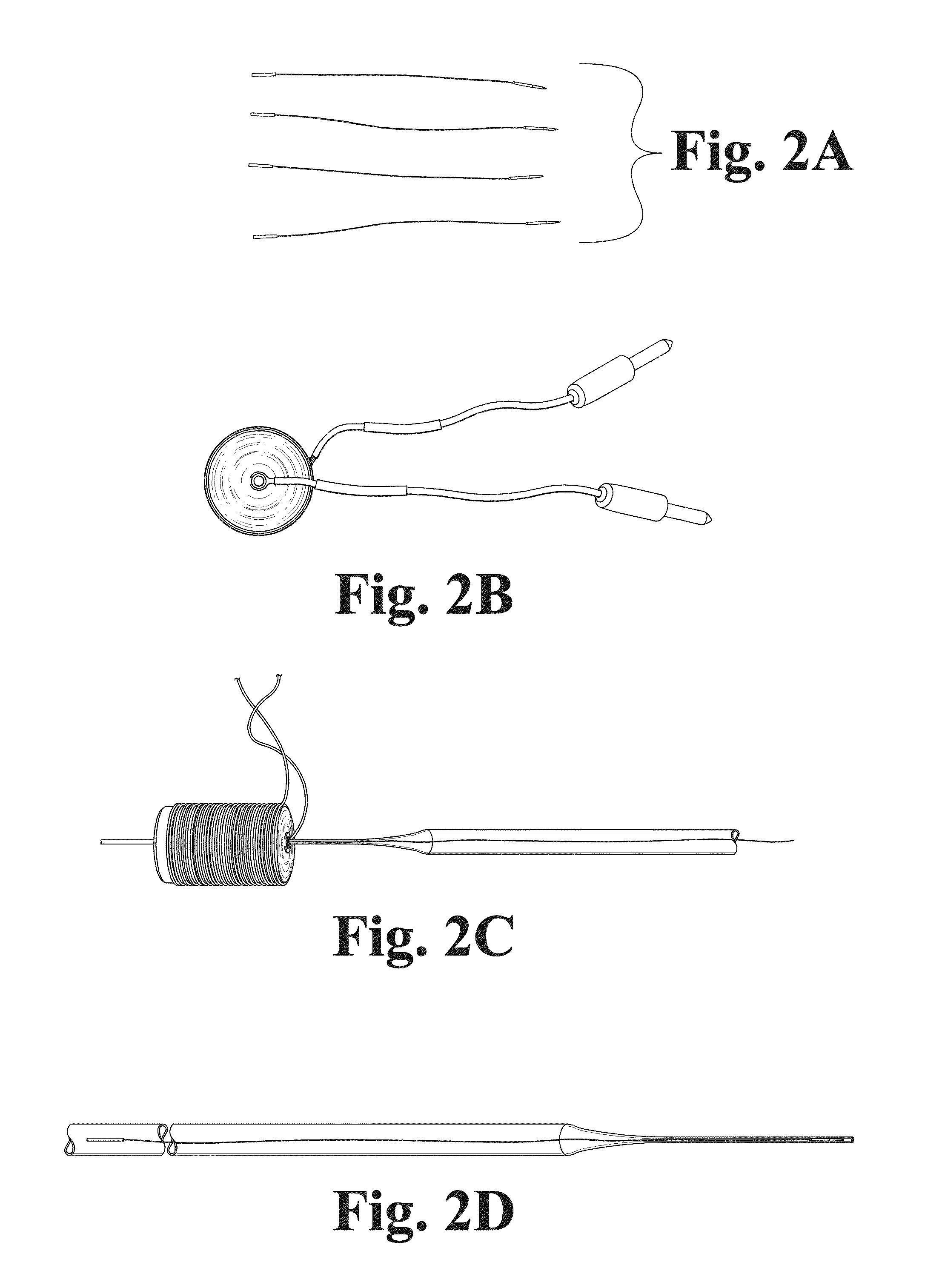
[0028]Referring to FIG. 1, a cross-sectional schematic of a prototype inductive coil and electrode constructed in accordance with certain aspects of the present invention is shown. Specifically, an inductive coil was constructed by wrapping 6 rows of 16 gauge copper heavy armored poly-thermaleze magnet wire (Belden) around a polyethylene spindle. The coil was measured to have an inductance of 110 μH and resistance of 118 mΩ. A small toroidal magnet was placed at one end of the coil to position the electrode prior to insertion, and a 9″ borosilicate glass Pasteur pipette (VWR) was inserted into the coil to act as the ejection tube...


PUM


Abstract

A neural probe deployment system comprising a magnetic probe, a magnetic field generator acting on the magnetic probe, a first guiding tube disposed on a first side of the magnetic field generator, wherein the magnetic probe is loaded inside the first guiding tube, and a second guiding tube disposed on a second side of the magnetic field generator, wherein activation of the magnetic field generator propels the magnetic probe from the first guiding tube through the second guiding tube, thereby deploying the magnetic probe.

Description

RELATED APPLICATIONS[0001]This application is a continuation of International Patent Application PCT / US09 / 66075 filed Nov. 30, 2009, which claims priority to U.S. Patent Application Ser. No. 61 / 118,628 filed Nov. 30, 2008, both of which are incorporated by reference herein.GOVERNMENT RIGHTS[0002]This invention was made with government support under Grant Number NA / IND010674 awarded by USDA / NIFA. The Government has certain rights in the invention.TECHNICAL FIELD OF THE DISCLOSURE[0003]The present invention relates generally to implantable electrodes, and more particularly, to flexible electrodes used with neural tissues.BACKGROUND OF THE DISCLOSURE[0004]Since their first use fifty years ago, chronic implantable electrodes have become a critical tool for exploring the function of neural tissue. In fact, chronic electrode recordings have contributed to the basic understanding of how neural networks process sensory stimuli and impart motor control. Moreover, these same electrodes can be...

Claims


Application Information

Patent Timeline
Patent Type & Authority Patents(United States)
IPC IPC(8): A61N1/00
CPCA61B5/053A61B1/00158A61B5/0478A61B5/0538A61B5/6868A61B2560/063A61B2562/0209A61N1/0534A61N1/0536A61N1/08A61B5/291A61B5/293
Inventor JAROCH, DAVID BENJAMINIRAZOQUI, PEDRORICKUS, JENNA LEIGH
Owner PURDUE RES FOUND INC
Why Eureka
Try Eureka