Magnetic adjustable turning loop
- Summary
- Abstract
- Description
- Claims
- Application Information
AI Technical Summary
Benefits of technology
Problems solved by technology
Method used
Image
Examples
Embodiment Construction
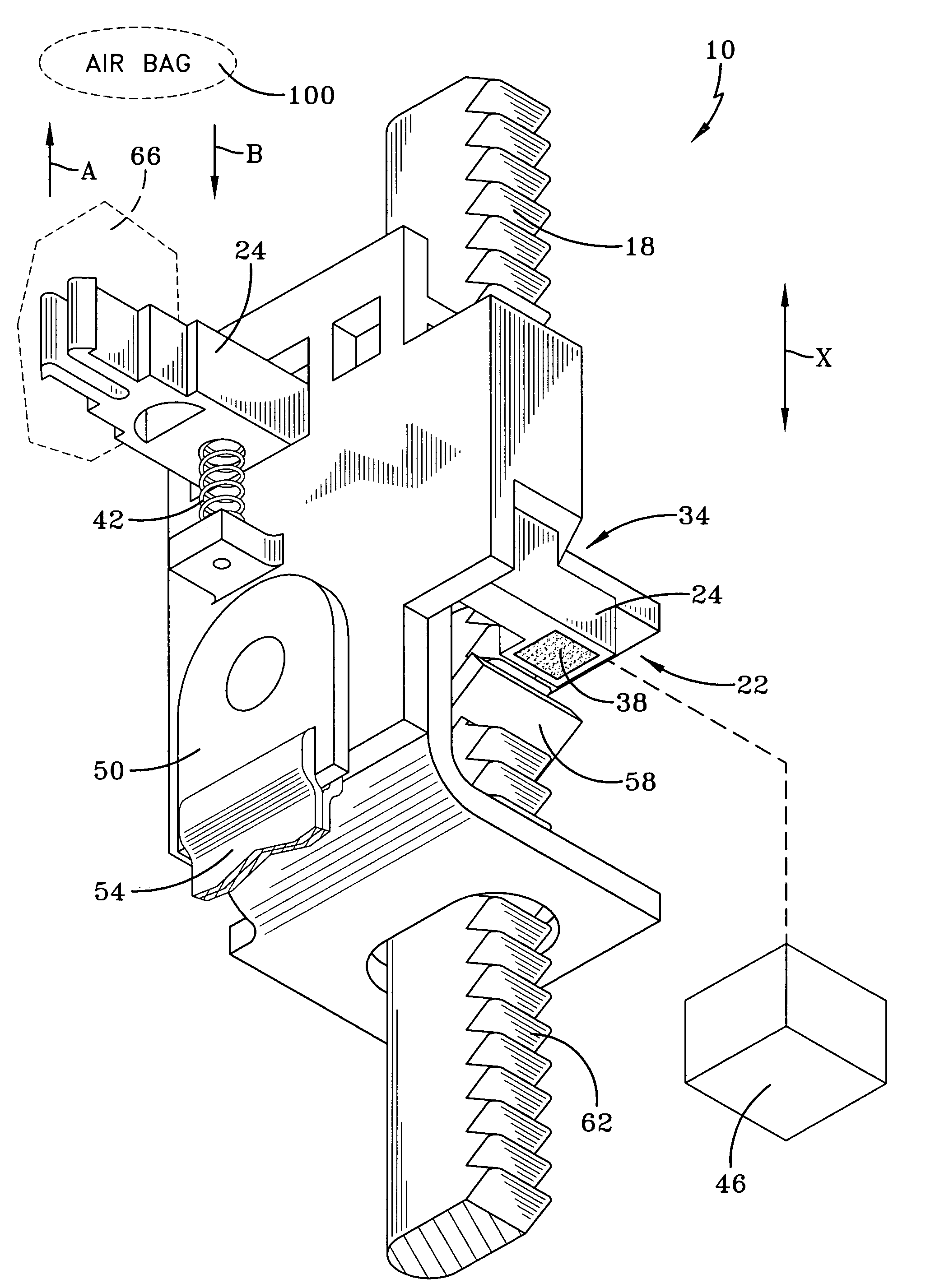
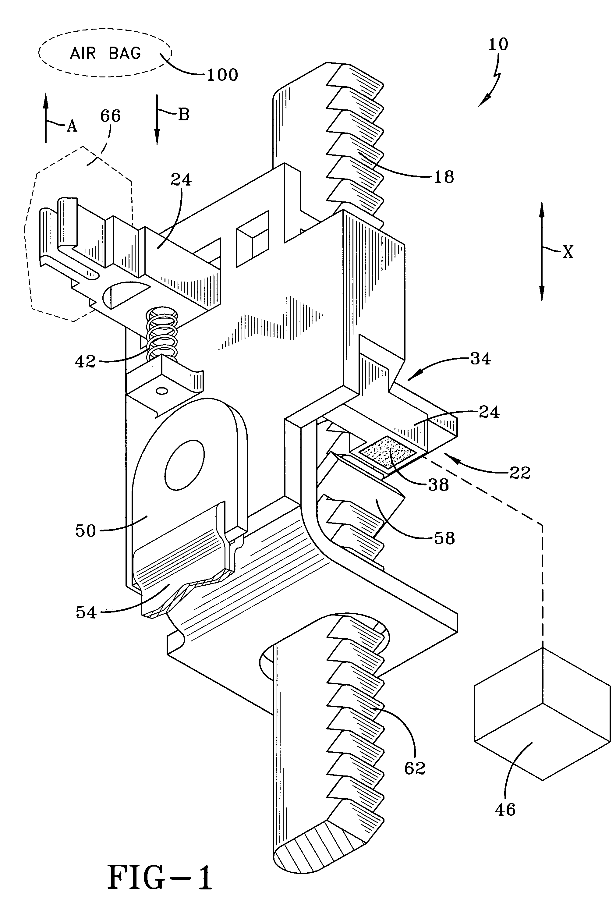
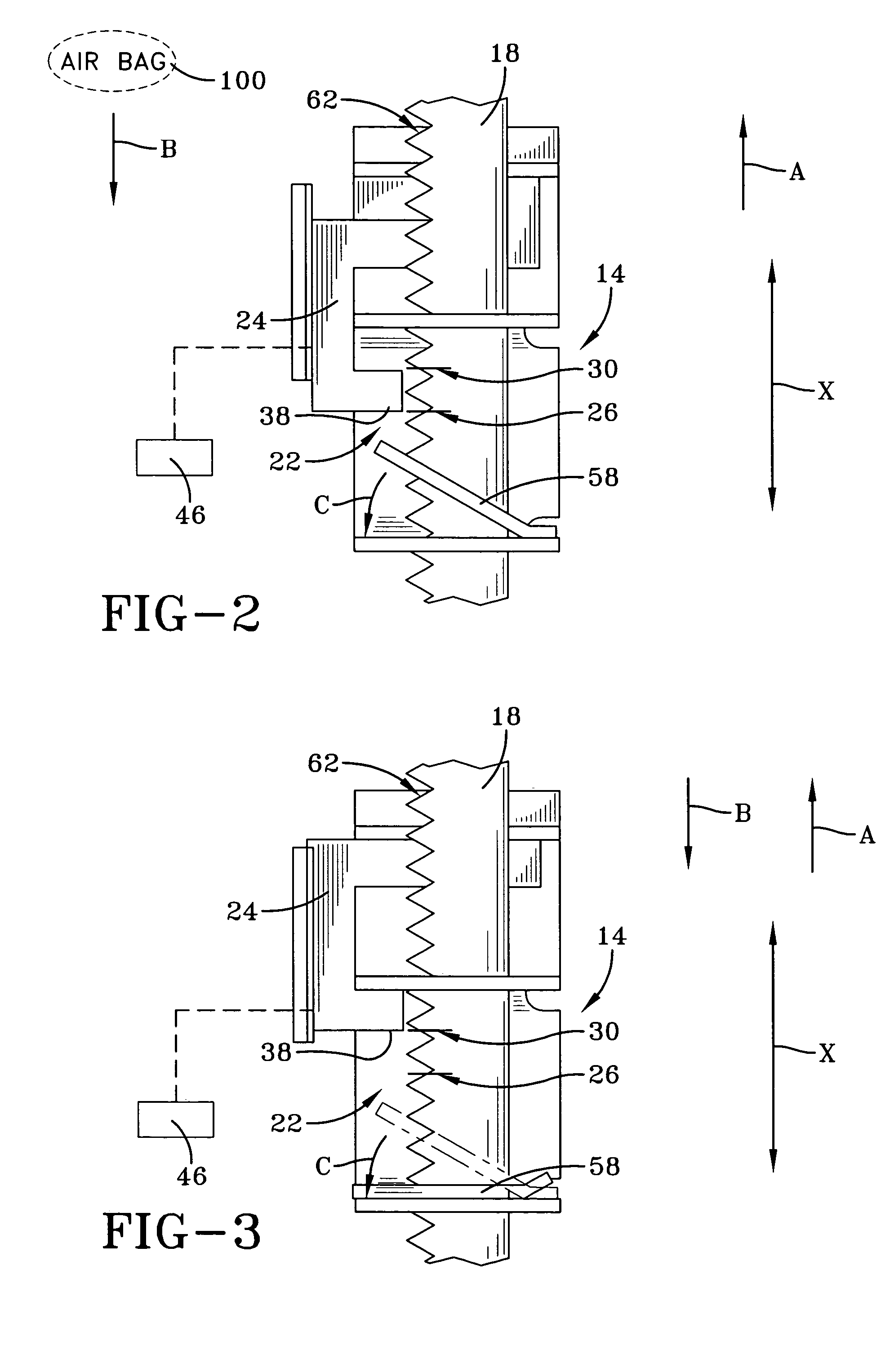
[0014]FIG. 1 illustrates a side view of the inventive adjustable turning loop or more broadly vehicle safety restraint adjuster 10. Vehicle safety restraint adjuster 10 comprises vehicle safety restraint support 14, here a slide, which slideably mounts loop 50 for shoulder belt 54 on rail 18. Slide 14 is adjustable along the X-axis in an up and down direction like existing adjustable turning loop assemblies. However, in contrast to such assemblies, vehicle safety restraint adjuster 10 is unlocked by moving button 66 (shown by dashed lines) in the direction of arrow A, an upward direction. Adjustable turning loop is locked by moving button 66 in the direction of arrow B. Accordingly, an air bag deploying from the window frame of a vehicle in the direction of arrow B only forces button 66 more towards its locked position. In addition, as shown in FIG. 1, spring 42 is biased to maintain button 66 in the locked position.
[0015]The inner working of vehicle safety restraint adjuster 10 wil...
PUM
 Abstract
Description
Claims
Application Information
 - R&D
- Intellectual Property
- Life Sciences
- Materials
- Tech Scout
- Unparalleled Data Quality
- Higher Quality Content
- 60% Fewer Hallucinations
Browse by: Latest US Patents, China's latest patents, Technical Efficacy Thesaurus, Application Domain, Technology Topic, Popular Technical Reports.
© 2025 PatSnap. All rights reserved.Legal|Privacy policy|Modern Slavery Act Transparency Statement|Sitemap|About US| Contact US: help@patsnap.com


