Electrical mullion

Inactive Publication Date: 2006-02-21
SPECIAL LITE
View PDF16 Cites 30 Cited by
  • Summary
  • Abstract
  • Description
  • Claims
  • Application Information

AI Technical Summary

Problems solved by technology

However, the top fitting utilized in this known arrangement projects a significant distance downwardly into the doorway when the mullion is removed which creates an obstruction when passing large objects through the doorway.
Further, the sleeve-like top fitting which houses the receptacle presents a space problem when connecting the power cable connector to the receptacle, since the installer must reach up into the top fitting to make the connection.
Since the sp

Method used


Image

  • Electrical mullion
  • Electrical mullion
  • Electrical mullion

Examples


Embodiment Construction

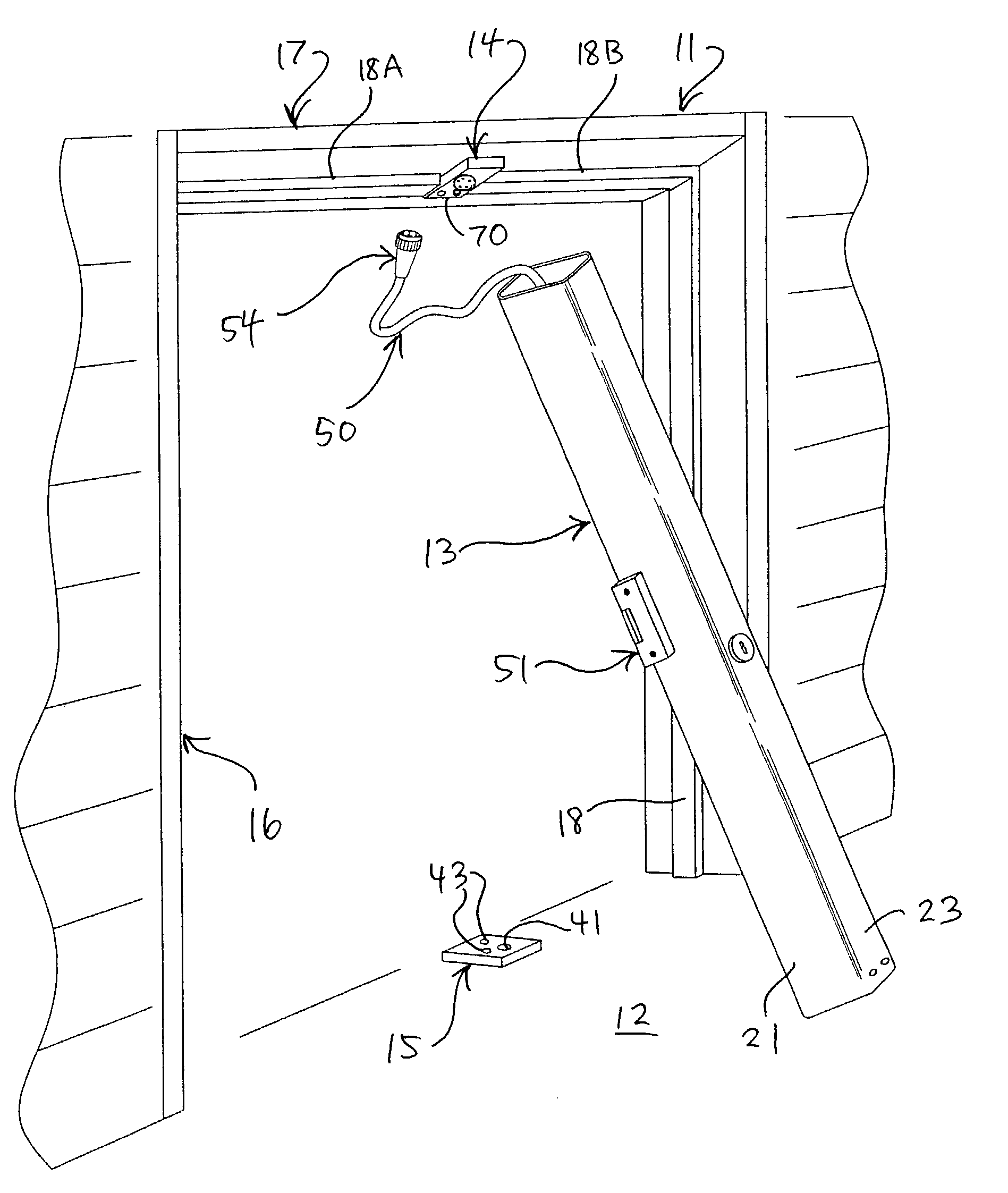
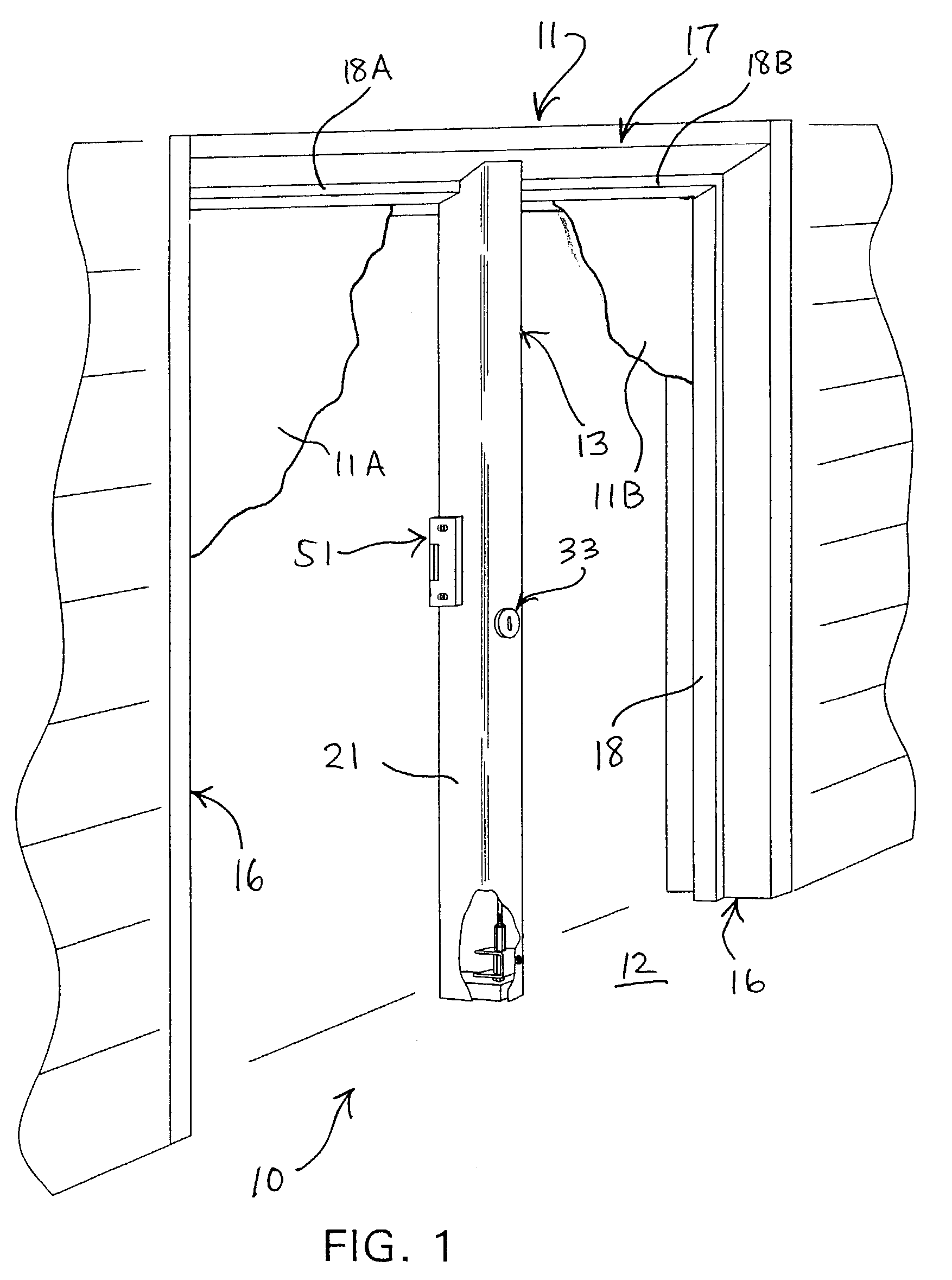
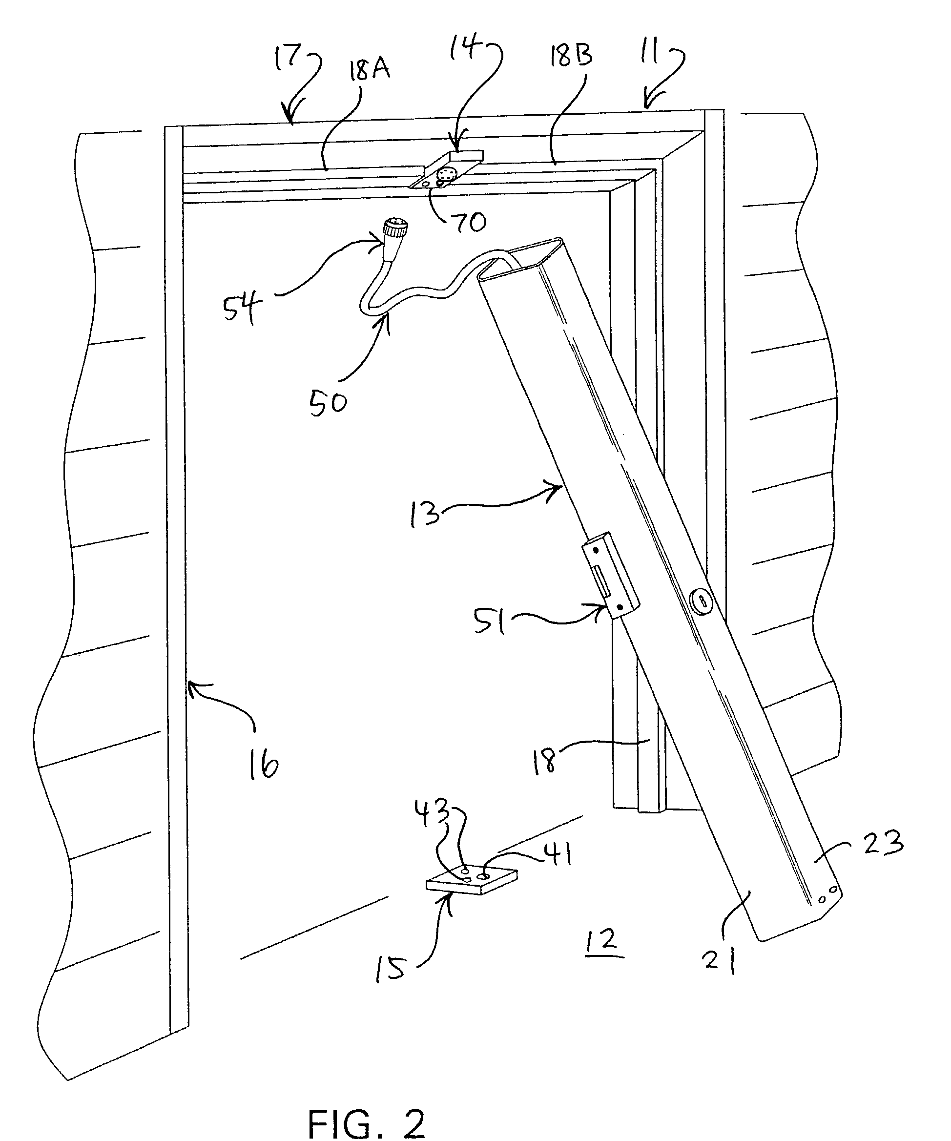
[0022]Referring to the drawings, FIG. 1 illustrates a mullion arrangement 10 installed between a double door frame 11 and a support surface such as a floor 12. A pair of doors 11A and 11B are conventionally disposed on opposite sides of the mullion arrangement 10 so as to close off the opening defined within the door frame 11, which are shown only partially in FIG. 1 for purposes of simplicity. Generally, the mullion arrangement 10 includes an elongate mullion 13 which extends between a top fitting 14 fixed to the door frame 11 and a bottom fitting 15 fixed to the floor 12 beneath the top fitting 14, as shown in FIGS. 2 and 3.

[0023]The door frame 11 is defined by a pair of generally parallel and upright side frame members 16 which are laterally spaced from one another by a generally horizontally oriented upper frame member or header 17 which extends between upper end portions of the side frame members 16. As is conventional, a door stop 18 extends longitudinally along each of the si...


PUM


Abstract

A mullion arrangement for mounting within a door frame including a top fitting secured to an upper frame member or header of the door frame, a bottom fitting secured to the floor beneath the top fitting, and a mullion removably positioned between the top and bottom fittings. The mullion defines therein a cavity which carries cabling therein for supplying power to a component associated with the entryway, such as an electric strike for regulating opening of the door.

Description

FIELD OF THE INVENTION[0001]This invention relates to a removable mullion arrangement for an entryway or doorway, and particularly pertains to a removable mullion arrangement having the capability of accommodating cabling for a component associated with the doorway.BACKGROUND OF THE INVENTION[0002]In many buildings, and particularly commercial buildings, double doors supported in metal frames are utilized. A vertically oriented mullion is often utilized in this type of frame so as to divide the double-door opening in half, and single doors are then mounted on opposite sides of the mullion. In many instances the mullion is mounted in a removable manner within the frame, which, after removal of the mullion from the frame, allows the movement of large objects or loads through the doorway.[0003]Due to increasing security and safety measures being taken with respect to various entryways to buildings, it is often desirable to incorporate security devices into doorways or to mount same adj...

Claims


Application Information

Patent Timeline
IPC IPC(8): E06B5/00E06B1/52
CPCE06B1/524
Inventor FLORY, LEO RAYMONDWALZ, DEWAIN D.CLARKE, JR., JAMES T.
Owner SPECIAL LITE
Why Eureka
Try Eureka