Rainproof recessed outlet box
a recessed outlet box and rainproof technology, applied in the direction of electrical apparatus casings/cabinets/drawers, lighting conductor installation, coupling device connection, etc., to achieve the effect of reducing the cost of outlet box production, and reducing the size of the box
- Summary
- Abstract
- Description
- Claims
- Application Information
AI Technical Summary
Problems solved by technology
Method used
Image
Examples
first embodiment
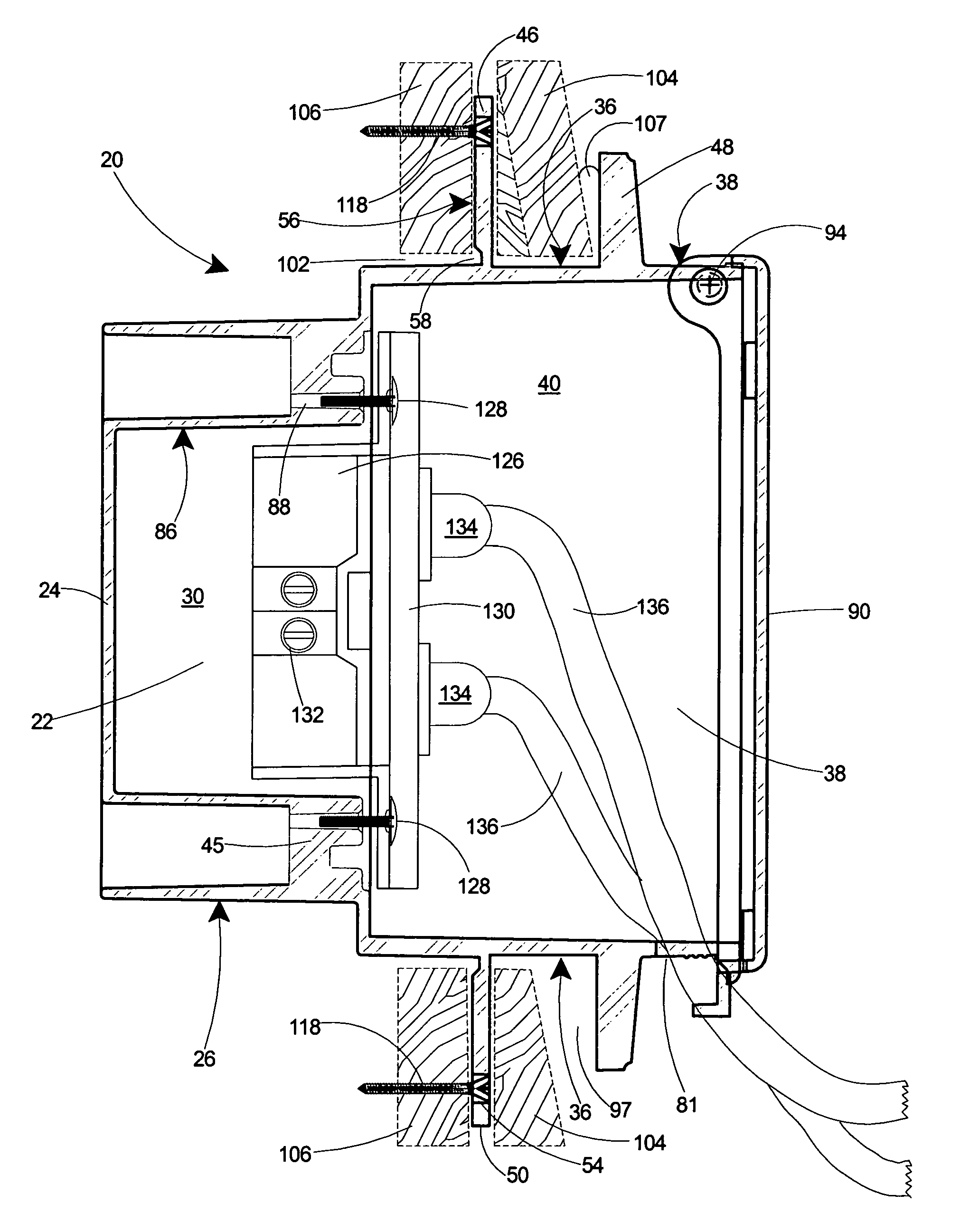
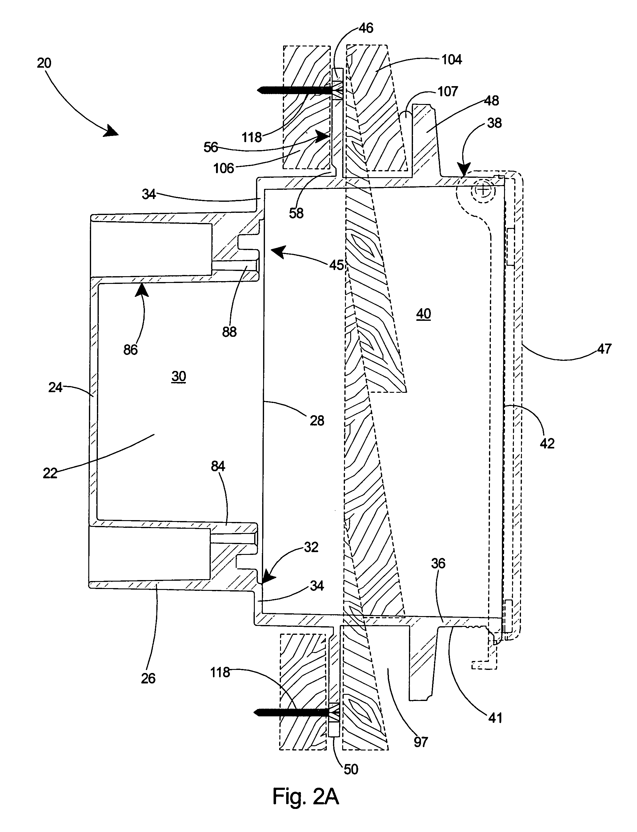
[0055]Referring to FIG. 17, the three embodiments of the recessed electrical box 20, 100, and 110 are shown installed on the outside surface 138 of a building. The flanges 46, 48 serve as a positioning arrangement 139 for positioning the electrical box 20, 100, 110 at the correct depth with respect to the wall. For the recessed electrical box 20, shown at the top of the figure, either the inner 46 or outer 48 flange serves as the positioning arrangement, depending on the application. If the siding 104 has not been installed, the installer simply makes a hole in the substrate 106 and pushes the box 20 into the hole until the rear surface of the inner flange 46 contacts the outer surface 140 of the substrate 106. Fasteners 118 are then driven through the inner flange 46 to secure the recessed electrical box 20 to the substrate 106. Siding 104 is then inserted into the gap 97 surrounding all four sides of the electrical box 20 and the siding 104 is then fastened to the substrate 106.
[0...
third embodiment
[0057]the recessed electrical box 110, shown at the bottom of FIG. 17, includes only a breakaway inner flange 46. If the building is under construction and the substrate 106 exposed, the inner flange 46 serves as a positioning arrangement for mounting the electrical box 110 at the proper depth. Fasteners 118 can then be driven through the inner flange 46 of the recessed electrical box 110 to secure it to the substrate 106.
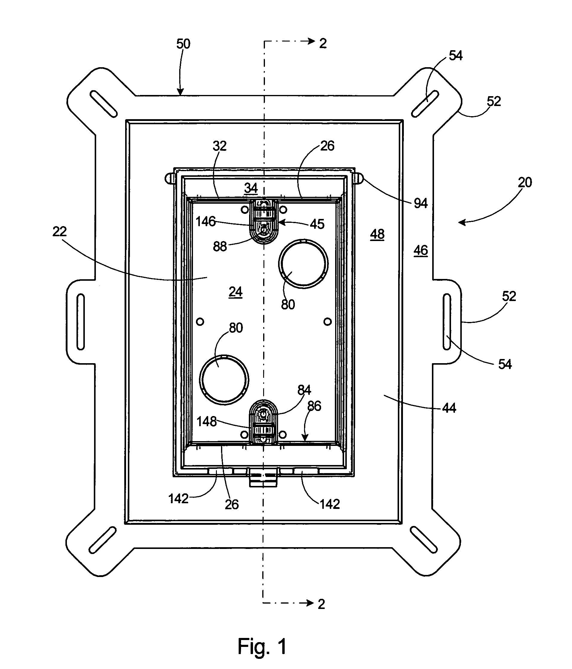
[0058]Regardless of which embodiment of the recessed electrical box 20, 100, 110 is used, the electrical device will be positioned substantially behind the outside surface 138 of the building, thereby providing a great deal of protection to the electrical device. As shown in FIG. 4, the planar front edge 42 of the recessed electrical box 20 further includes one or more U-shaped slots 142 in the side walls 36 of the second box 38. As shown in FIG. 13, the cover member 47 also includes one or more U-shaped slots 144 in the stiffening side wall 95. When the cover memb...
PUM
 Abstract
Description
Claims
Application Information
 - R&D
- Intellectual Property
- Life Sciences
- Materials
- Tech Scout
- Unparalleled Data Quality
- Higher Quality Content
- 60% Fewer Hallucinations
Browse by: Latest US Patents, China's latest patents, Technical Efficacy Thesaurus, Application Domain, Technology Topic, Popular Technical Reports.
© 2025 PatSnap. All rights reserved.Legal|Privacy policy|Modern Slavery Act Transparency Statement|Sitemap|About US| Contact US: help@patsnap.com


