
Automatic hitch assembly

a technology of automatic and tongue disengagement, which is applied in the field of hitches, can solve the problems of difficult disengagement from an engaged tongue, unfavorable ergonomics or advantageous use of body weight by the operator, and unfavorable disengagement of the hitch from the tongue, etc., and achieve the effect of improving the previous hitch assembly

Inactive Publication Date: 2006-03-14
TOYOTA MOTOR ENGINEERING & MANUFACTURING NORTH AMERICA
View PDF15 Cites 16 Cited by
  • Summary
  • Abstract
  • Description
  • Claims
  • Application Information

AI Technical Summary

Benefits of technology

The present invention aims to improve previous hitch assemblies by providing an automatic hitch with a biasing member that normally pushes the jaw assembly towards the support surface in its engaged position. The hitch also includes a release mechanism that can be actuated to move the jaw assembly to a disengaged position. The method for releasing a tongue from a hitch involves applying downward force on one end of the release mechanism and creating an upward force on the opposite end to move the jaw assembly to a disengaged position. The invention can be used in different ways and has various advantages.

Problems solved by technology

Issues arise with such bottom action jaws when the spring loses its resilience and / or when the device is subjected to sudden jars such as are common from bumps along the path of travel.
Such occurrences can lead to undesirable and potentially harmful situations.
Another issue arises with such hitch assemblies in that they can be difficult to disengage from an engaged tongue.
Often, the release mechanism must be forced upward or sideways to release the jaw from the tongue, and therefore, does not allow an operator to ergonomically or advantageously use his / her body weight to disengage the hitch from the tongue.

Method used


Image

  • Automatic hitch assembly
  • Automatic hitch assembly
  • Automatic hitch assembly

Examples


Embodiment Construction

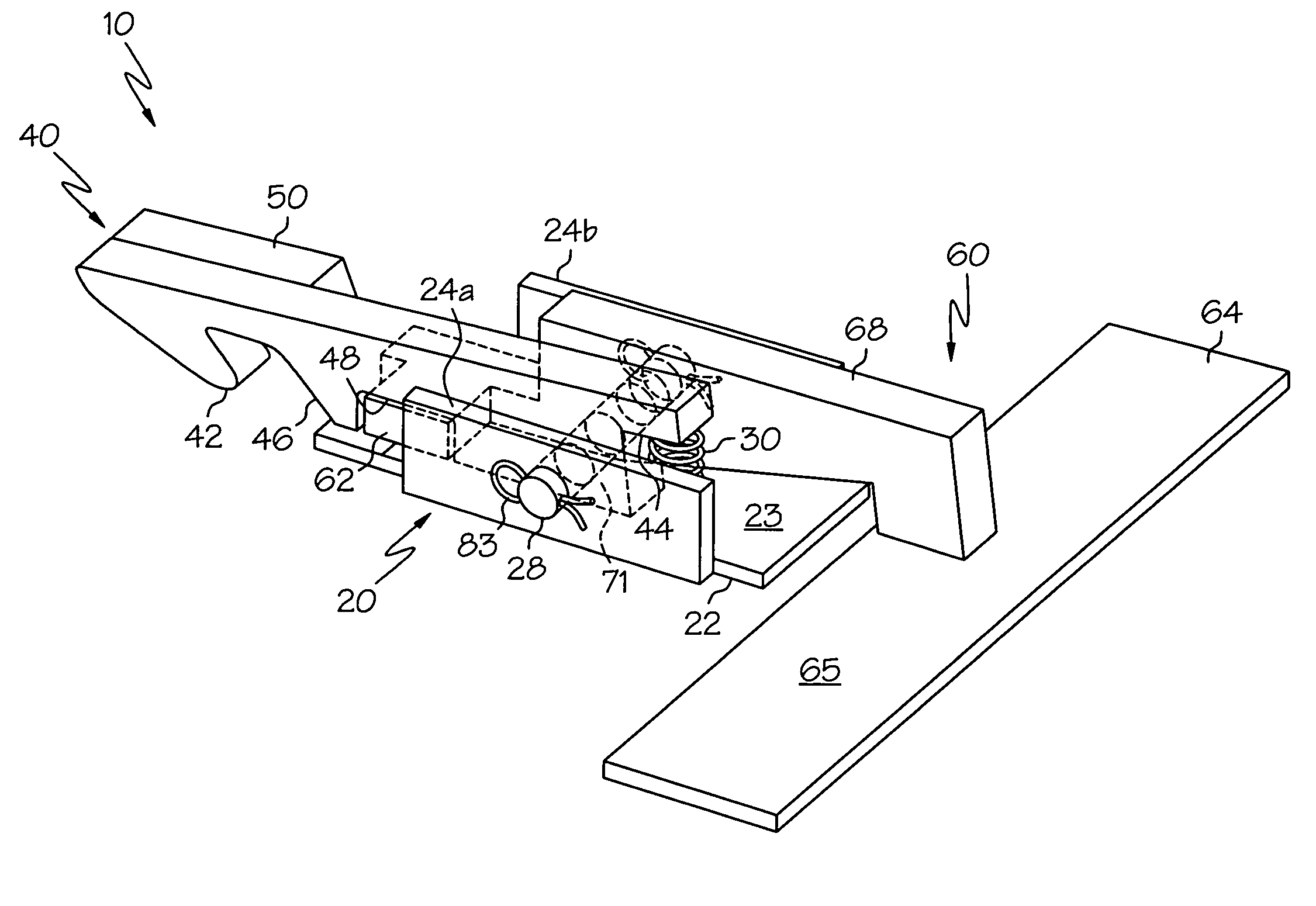
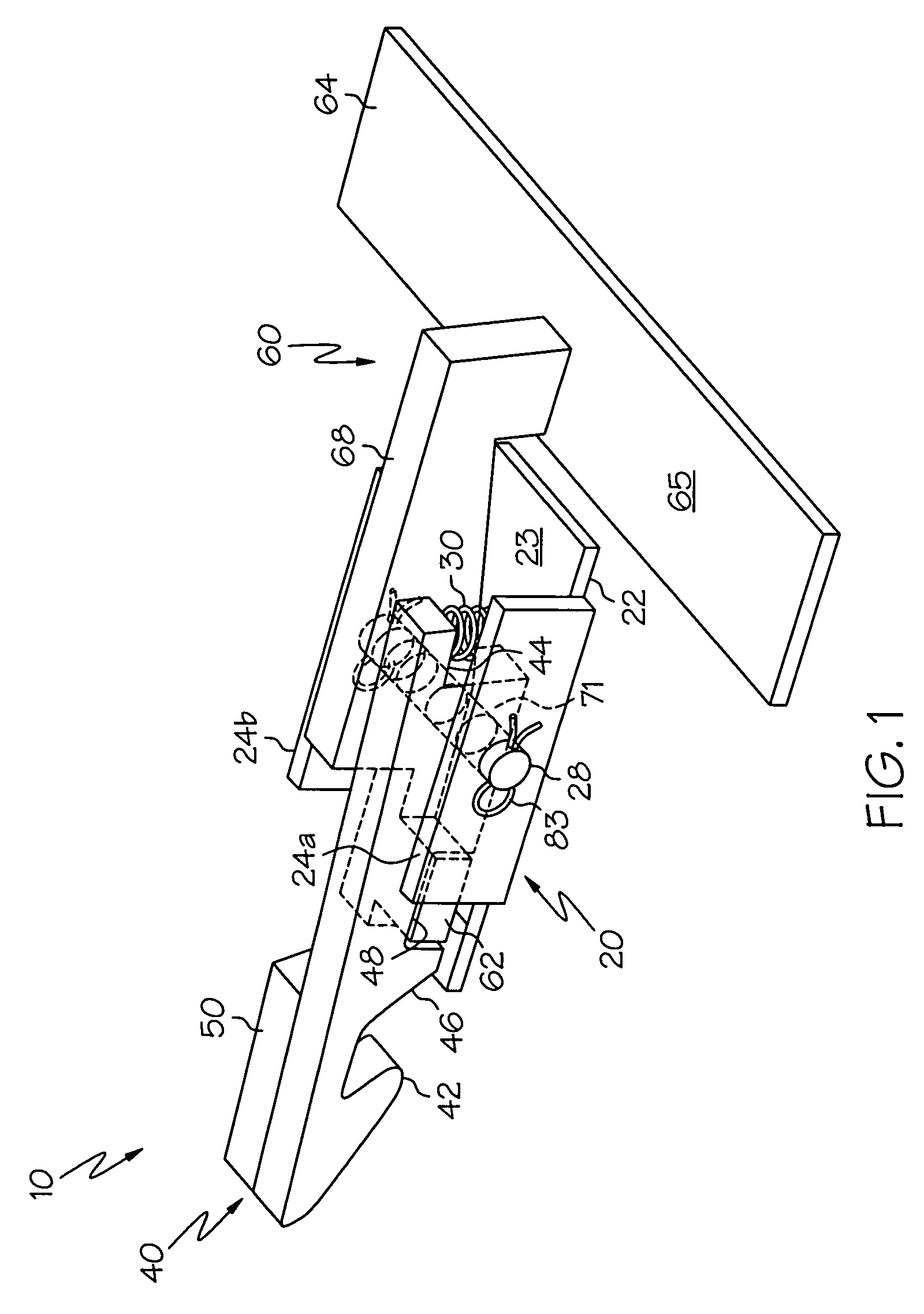
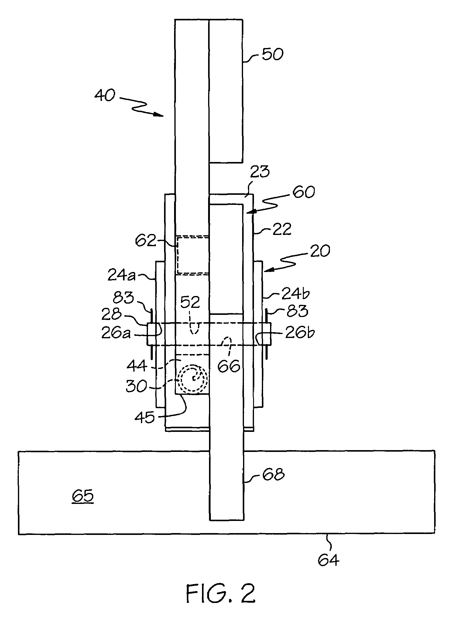
[0014]Referring to the drawing figures in detail, wherein like numerals indicate the same elements throughout the drawing figures, FIG. 1 illustrates an exemplary automatic hitch assembly 10 as generally having a base 20, a jaw assembly 40 and a release mechanism 60. Hitch assembly 10 and components thereof may be comprised of metal, plastic and / or any combination of durable materials.

[0015]As illustrated in FIGS. 1–3, base 20 may comprise a lower plate 22 with two walls 24a and 24b extending upwardly at about a 90° angle therefrom. Lower plate 22 may comprise any length and / or width and include a support surface 23. Support surface 23 may function as a lowermost support or “stop” for jaw assembly 40 adjacent to stopping member 46 when in an engaged position (as illustrated in FIG. 1). In another embodiment, lower surface 22 and support surface 23 may extend to or beyond hook 42 of jaw assembly 40 thereby providing a similar support or “stop” surface for hook 42 and / or a tongue of a...


PUM


Abstract

An automatic hitch may include a base, a support surface, a jaw assembly connected to the base and having engaged and disengaged positions and a biasing member associated with the jaw assembly. The biasing member may be configured to normally bias the jaw assembly toward the support surface. The automatic hitch may also include a release mechanism configured to apply upward force to the jaw assembly upon downward actuation of the release mechanism to move the jaw assembly into the disengaged position.

Description

FIELD OF THE INVENTION[0001]This invention relates to a hitch for joining a trailer to a vehicle. More particularly, this invention relates to an ergonomically improved easy to operate hitch assembly having an automatic top action jaw.BACKGROUND OF THE INVENTION[0002]A variety of hitch assemblies for securing trailers to vehicles are known. One such assembly includes a bottom action jaw design having a spring-loaded arm configured to grasp a bail or tongue of a trailer from the bottom.[0003]Issues arise with such bottom action jaws when the spring loses its resilience and / or when the device is subjected to sudden jars such as are common from bumps along the path of travel. For example, because the spring biases the arm upward, loss of spring resiliency or bounce from a bump may cause the arm to drop out of the jaw thereby allowing disengagement of the tongue and a connected trailer(s). Such occurrences can lead to undesirable and potentially harmful situations.[0004]Another issue ar...

Claims


Application Information

Patent Timeline
Patent Type & Authority Patents(United States)
IPC IPC(8): B60D7/00B60D99/00B60D1/02B60D1/26
CPCB60D1/26B60D1/02
Inventor BLANTON, JEFFREY W.
Owner TOYOTA MOTOR ENGINEERING & MANUFACTURING NORTH AMERICA
Learn More