
Chair with flexible, resilient back support

a back support and flexible technology, applied in the field of chairs, can solve the problems of not being suitable for stackable chairs, large reclining mechanisms that have been developed, and complicated reclining mechanisms, and achieve the effect of increasing the effective flexural resistance of the spring elemen

Inactive Publication Date: 2006-04-04
MITY-LITE
View PDF28 Cites 32 Cited by
  • Summary
  • Abstract
  • Description
  • Claims
  • Application Information

AI Technical Summary

Benefits of technology

"The present invention is a chair with a hollow tubular seat frame and a hollow tubular backrest frame that pivots at fixed points. It also has a limit stop that controls the rotation of the backrest frame and a spring element that pushes the backrest frame back to its original position. The spring element has a curved lower surface that acts as a fulcrum point, making it more resistant to backward rotation. This design provides better flexural resistance and ensures the chair is stable and secure during use."

Problems solved by technology

Some of these involve very complicated reclining mechanisms.
Unfortunately, many of the reclining mechanisms that have been developed are not suitable to simple, relatively low-cost chairs, such as stackable banquet or meeting hall chairs.
A bulky reclining mechanism is not suitable for stackable chairs, and an expensive mechanism is not desirable for locations such as hotels and the like, which require large numbers of chairs for banquets, conferences, etc.
Another problem with some simple reclining back chairs is the location where the chair reclines or bends.
Both of these motions do not adequately address the structure and motion of the human body.
Additionally, some reclining mechanisms, particularly the more simple ones, present pinch points where a user's fingers or other items can get caught.
While there are various methods that have been devised for reducing, or hiding pinch points, many prior solutions have not adequately addressed the problem in an effective and inexpensive manner.

Method used


Image

  • Chair with flexible, resilient back support
  • Chair with flexible, resilient back support
  • Chair with flexible, resilient back support

Examples


Embodiment Construction

[0023]Reference will now be made to the exemplary embodiments illustrated in the drawings, and specific language will be used herein to describe the same. It will nevertheless be understood that no limitation of the scope of the invention is thereby intended. Alterations and further modifications of the inventive features illustrated herein, and additional applications of the principles of the inventions as illustrated herein, which would occur to one skilled in the relevant art and having possession of this disclosure, are to be considered within the scope of the invention.

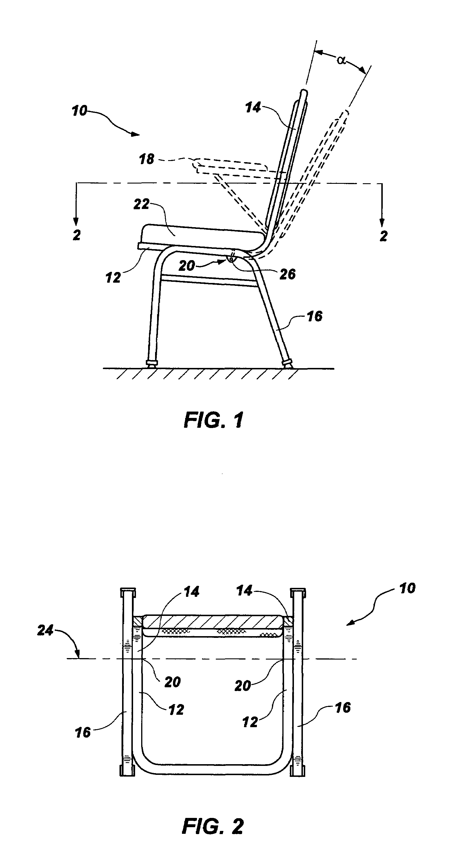
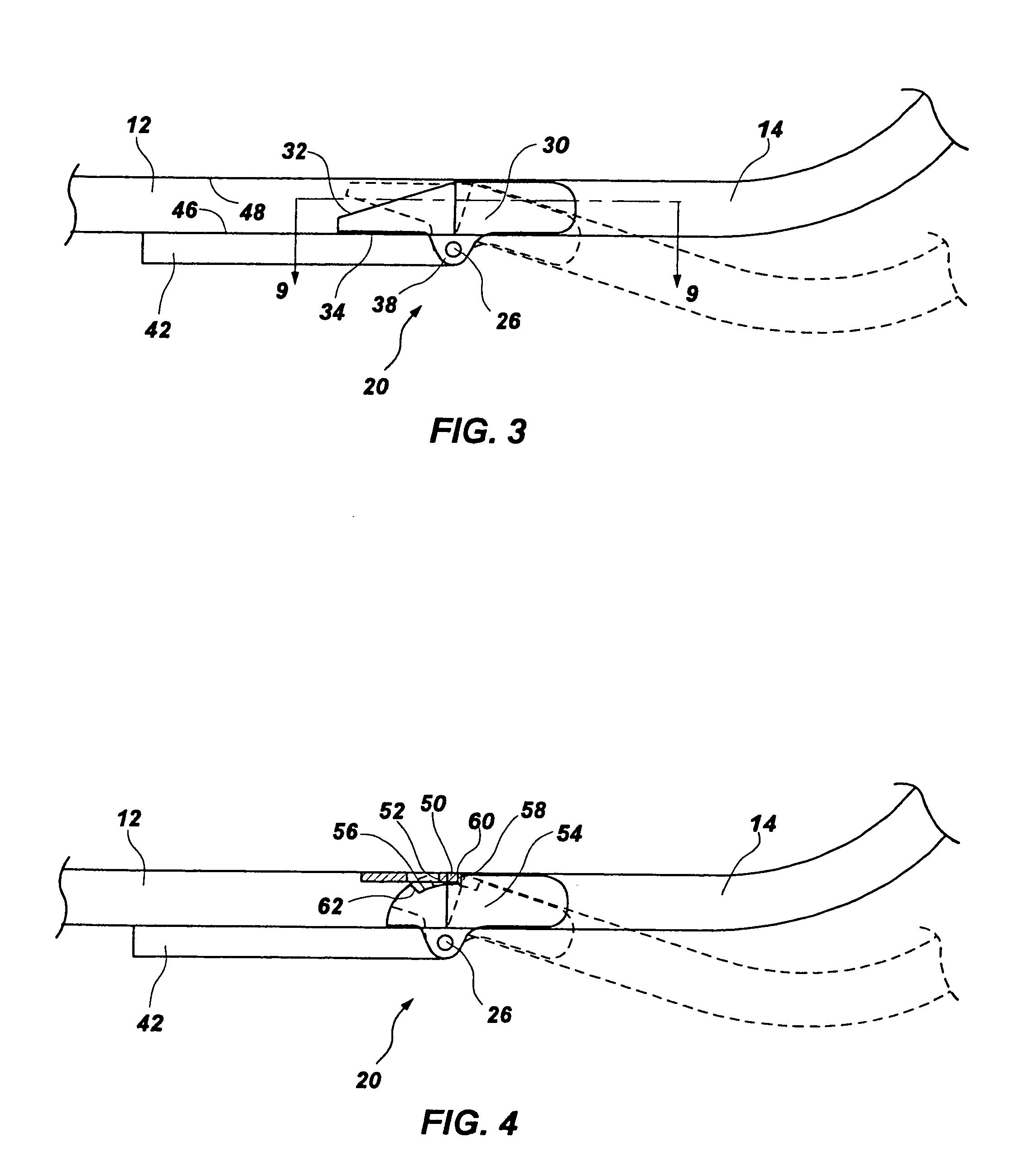
[0024]Referring to FIG. 1 and FIG. 2, the present invention is depicted as applied to a common type of stackable banquet chair 10. It will be apparent, however, that the present invention is also adaptable to many other types of chairs. The chair 10 includes a hollow tubular seat frame 12, and a hollow tubular backrest frame 14. In typical stackable banquet chairs, the backrest frame is an extension of the seat f...


PUM


Abstract

A chair with a flexible resilient back support structure includes a hollow tubular seat frame, a hollow tubular backrest frame pivotally connected to the seat frame, and a limit stop affixed to the backrest frame or the seat frame adjacent to the pivot points. The limit stop is configured to limit a degree of rotation of the backrest frame between an upright position and a maximum backwardly rotated position. An elongate spring element extends from within the backrest frame into the seat frame, and is configured to bias the backrest frame in the upright position, and to resiliently resist backward rotation. In various embodiments, a cam surface is associated with the spring element, providing an effective fulcrum point which moves rearwardly as the backrest frame reclines, thereby increasing the effective flexural resistance of the spring element during reclining.

Description

CROSS REFERENCE TO RELATED APPLICATION(S)[0001]This is a Division of application Ser. No. 10 / 213,602, filed on Aug. 6, 2002, now U.S. Pat. No. 6,779,846.BACKGROUND OF THE INVENTION[0002]1. Field of the Invention[0003]The present invention relates generally to chairs with flexible backrests. More particularly, the present invention relates to a chair having a back support structure that is resiliently hingedly coupled to the seat and supporting structure.[0004]2. Related Art[0005]Reclining chairs are generally considered more comfortable than non-reclining chairs. Of the variety of reclining chairs, some comprise a chair with a fixed seat and a backrest that is configured to flex or recline backward relative to the seat. There are a variety of types of chairs with flexible or reclining backrests. Some of these involve very complicated reclining mechanisms. Some involve flexible members that bend along their length, while others include relatively rigid frame components that are hinge...

Claims


Application Information

Patent Timeline
Patent Type & Authority Patents(United States)
IPC IPC(8): A47C7/44
CPCA47C7/445
Inventor SPENDLOVE, DALEHARDY, LOUIS N.
Owner MITY-LITE
Learn More