Transmission

a technology for working machines and transmission lines, applied in transportation and packaging, tilling equipment, gearing, etc., can solve the problems of increasing cost and weight, and achieve the effects of improving the operability of the shift lever, facilitating engagement, and smooth connection

Inactive Publication Date: 2006-04-18
HONDA MOTOR CO LTD
View PDF12 Cites 723 Cited by
  • Summary
  • Abstract
  • Description
  • Claims
  • Application Information

AI Technical Summary

Benefits of technology

[0025]A driving torque of the working transmission mechanism causes the first gear to rotate with respect to the working transmission shaft, causing the engaging piece to contact an inner wall of a circumferential edge of the recess formed in the first gear, thereby transmitting power from the working transmission shaft to the first gear.
[0026]As described above, instead of only connecting the gear integrally mounted on the working transmission shaft to the second gear via the coupling member, the present invention includes the clutch mechanism having the tapers at the teeth of the coupling member and the teeth of the second gear and having the recess provided in the first gear which allows the engaging member to move at a predetermined angle in a rotative direction of the working transmissio

Problems solved by technology

The synchromesh transmission mechanism, however, has a large number of com

Method used


Image

  • Transmission
  • Transmission
  • Transmission

Examples


second embodiment

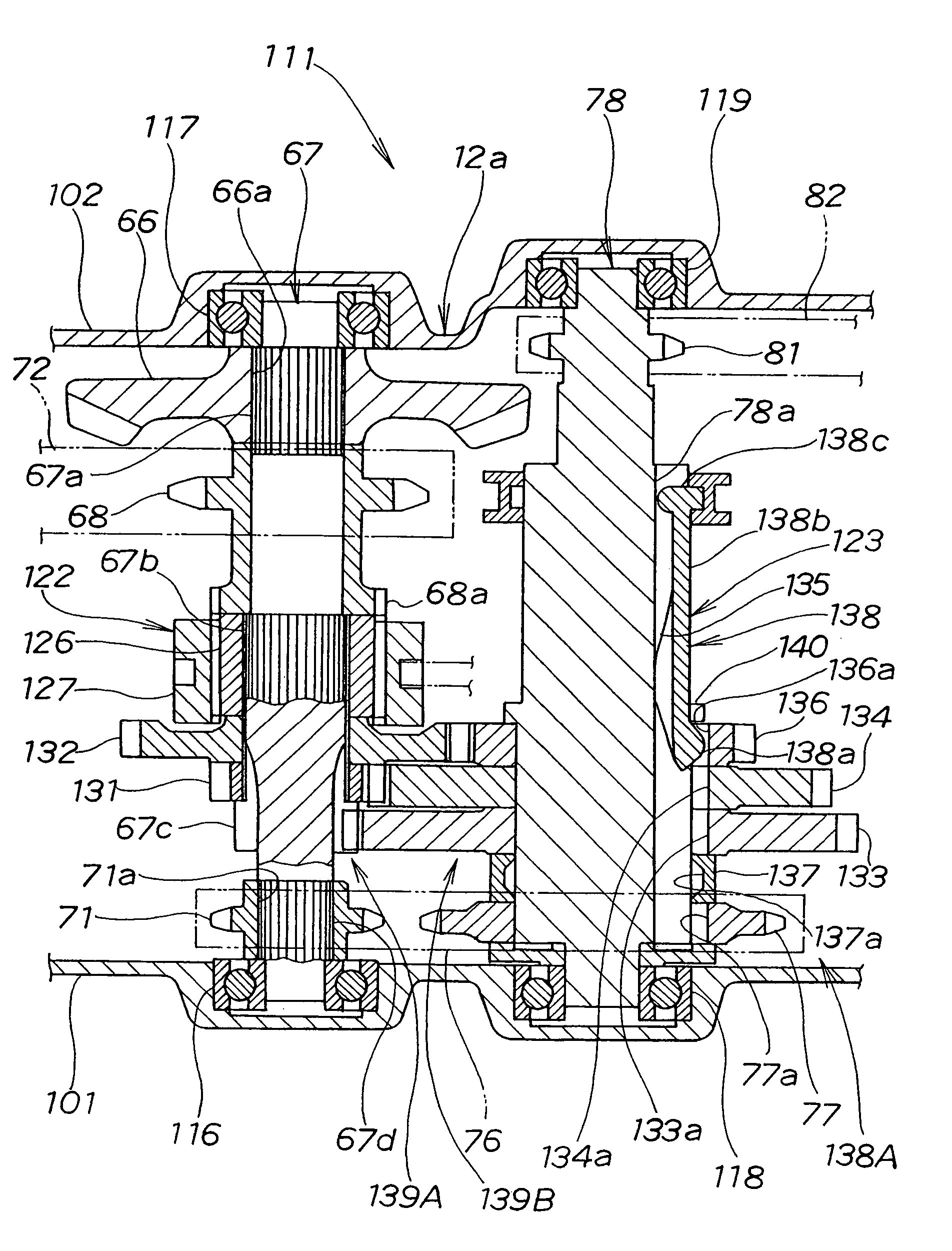
[0176]FIG. 20 illustrates the first drive sprocket 68, a coupling sleeve 127, the input gear 126 and the clutch mechanism 124 which constitute the working transmission mechanism 122 shown in FIG. 19.

[0177]The input gear 126 is fitted on a working shaft 67. The clutch mechanism 124 restricts the rotation of the input gear 126 with respect to the working shaft 67. Teeth 126b formed on the input gear 126 engage with teeth 127a formed in the coupling sleeve 127. Axial sliding of the coupling sleeve 127 causes the teeth 127a of the coupling sleeve 127 to engage with teeth 68c of a gear 68a of the first drive sprocket 68. That is, the clutch mechanism 142 transmits torque of the working shaft 67 to the first drive sprocket 68 or cuts off.

[0178]The clutch mechanism 124 consists of a through hole 67f, a shaft recess 67g, a spring (biasing member) 141, a ball (protruding member) 142, a cylindrical member (engaging member) 143, a first groove (cam) 126d, and a second groove (recess) 126e.

[0...

third embodiment

[0226]In the third embodiment shown in FIG. 27A, the hole 67f is formed in the working shaft 67, the shaft recess 67g is formed at an end of the hole 67f, and the key 211 is disposed in the shaft recess 67f The present invention is not limited thereto. It is also possible to movably dispose a cylindrical key within the hole 67f without providing the shaft recess 67g.


PUM


Abstract

A transmission for a working machine including a drive transmission mechanism and a working transmission mechanism operated by swinging a shift lever is provided. The drive transmission mechanism has a key-sliding transmission mechanism axially mounted on a drive shaft. The key-sliding transmission mechanism causes a selected one of a plurality of gears rotatably mounted on the drive shaft and the drive shaft to rotate together to transmit power to drive wheels.

Description

FIELD OF THE INVENTION[0001]The present invention relates to transmissions for farm working machines and the like.BACKGROUND OF THE INVENTION[0002]A transmission having a selective-sliding transmission mechanism in which operation of a lever causes a main gear to engage with a selected gear is disclosed, for example, in Japanese Utility Model Laid-Open Publication No. HEI-6-43561.[0003]This transmission using the selective-sliding transmission mechanism will be described with reference to FIGS. 29 and 30.[0004]The transmission shown in FIG. 29 includes an input shaft 402 as a first shaft, second shaft 403, third shaft 404 and output shaft 405 which are rotatably supported in a case 401.[0005]On the input shaft 402, gears 406 and 407 are mounted. On the second shaft 403, gears 408 and 409 are rotatably mounted in constant mesh with the gears 406 and 407. A mechanical clutch 410 for selectively connecting the second shaft 403 to either of the gears 408 and 409 is provided between the ...

Claims


Application Information

Patent Timeline
IPC IPC(8): F16H3/08B60K17/06A01B33/08F16H3/083
CPCA01B33/082F16H3/083Y10T74/19372Y10T74/19251Y10T74/1947Y10T74/19479Y10T74/19288F16H3/001B60K17/06
Inventor OHTA, YOSHITAKAKANBARA, FUMIYOSHI
Owner HONDA MOTOR CO LTD
Why Eureka
Try Eureka