
Motor vehicle comprising a drive train having a multiple clutch drive

a technology of drive train and clutch drive, which is applied in the direction of gearing, couplings, tractors, etc., can solve the problems of high drag torque (as high as 25 nm), drag torque persists until the viscosity of oil has decreased, and it is impossible in practice to engage a gear

Inactive Publication Date: 2004-06-17
VOLKSWAGEN AG +1
View PDF0 Cites 84 Cited by
  • Summary
  • Abstract
  • Description
  • Claims
  • Application Information

AI Technical Summary

Benefits of technology

[0013] One might ask what the purpose could be of engaging several gears assigned to the same gearbox input shaft. This measure, however, gives the driver the opportunity, when starting the vehicle, to choose the gear which is especially suitable for driving off in the specific situation from among the gears assigned to the gearbox input shaft in question. The other gears would then be disengaged. Another concrete possibility of using this measure is derived from the fact that the gearbox is blocked when two gears assigned to the same gearbox input shaft are engaged. It is proposed that this effect can be exploited to provide the vehicle with a "parking brake". The control unit can therefore be designed to automatically engage at least two gears assigned to the same gearbox input shaft by means of the actuator arrangement in response to the parking of the vehicle in such a way that the gearbox is blocked and thus acts as a parking brake for the vehicle.
[0104] To prepare for or to facilitate the engagement of a gear, it is proposed that a / the control unit be designed to operate the drive unit at a speed significantly faster than the idling speed for a predetermined time period to prepare for the engagement of at least one gear and / or during the engagement of the minimum of one gear while at least one clutch arrangement is disengaged and / or when no more than one gear is engaged to remove operating fluid from the disks of the clutch arrangements by the effect of centrifugal force. Thus, after the engine has been started, it is possible to facilitate the engagement of the gear--in the situation that no gear is or has been engaged--by increasing the engine rpm's in order to use the effect of the now increased centrifugal force acting on the operating fluid (the cooling oil) to spin free the set or sets of disks and thus to reduce the drag torques, which makes it easier to engage the gear. This inventive proposal is also of general interest.

Problems solved by technology

, as may be the case, for example, after the motor vehicle has been shut off overnight in the winter, there is a drastic increase in the viscosity of the oil, resulting in very high drag torques (as high as 25 Nm). I
fter these disks have been separated, however, the drag torques persist until the viscosity of the oil has decreased as a result of the warming-up of the engine and the introduction of heat (frictional energy) into the clutch arrangements.
As a result these high drag or adhesion torques, it can become impossible in practice to engage a gear, because the synchronizing devices of the gearbox are usually not designed to overcome such high torques.
If no gears can be engaged or shifted, it is not possible to drive the vehicle.

Method used


Image

  • Motor vehicle comprising a drive train having a multiple clutch drive
  • Motor vehicle comprising a drive train having a multiple clutch drive
  • Motor vehicle comprising a drive train having a multiple clutch drive

Examples


Embodiment Construction

[0007] The present invention also has the goal of solving or at least reducing the severity of the problems discussed above, and in particular of making it easier to control them.

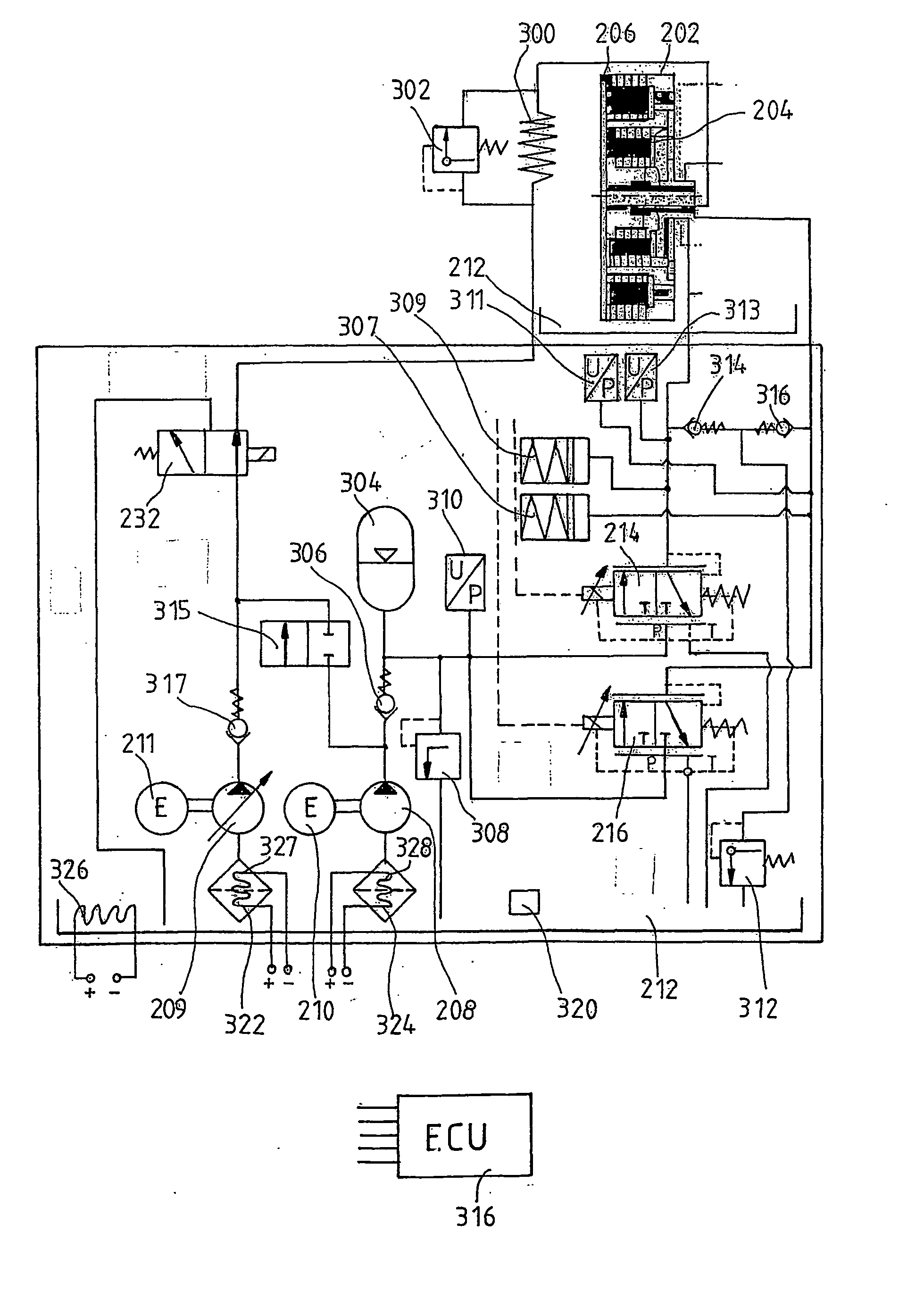
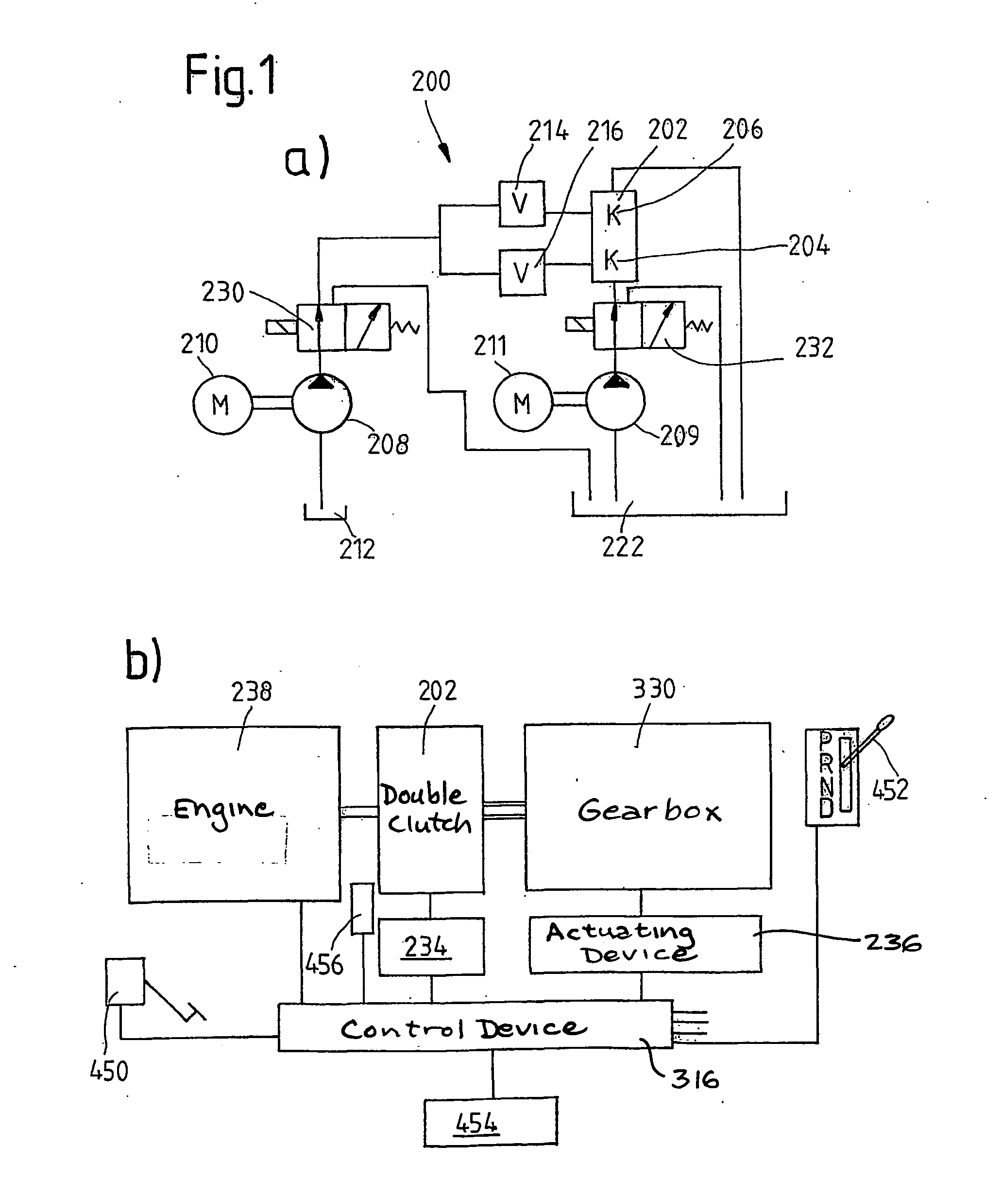
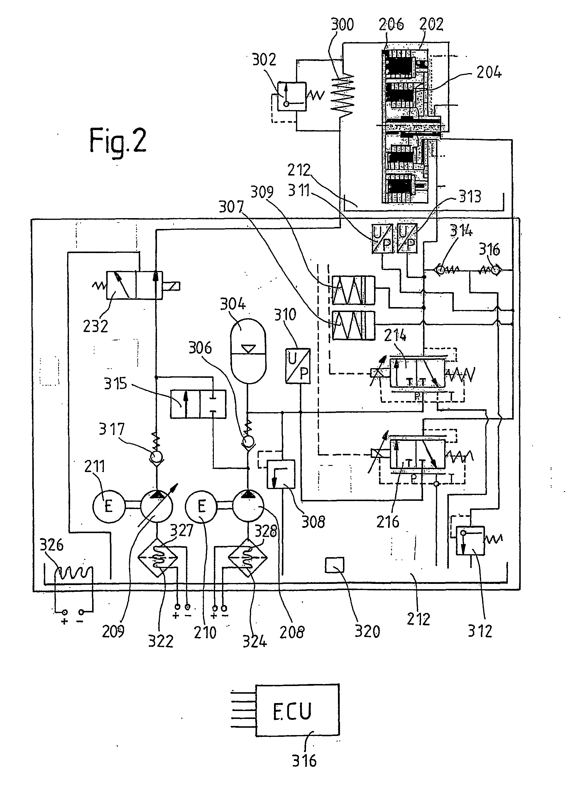
[0008] In accordance with a first primary aspect, a motor vehicle comprising a power train which has: a drive unit; a gearbox with a first gearbox input shaft and a second gearbox input shaft; and a clutch device with a first clutch arrangement, which is assigned to the first gearbox input shaft, and a second clutch device, which is assigned to the second gearbox input shaft, for the transmission of torque between the drive unit and the gearbox; wherein the clutch arrangements are designed as disk clutch arrangements, to which an operating fluid, especially a cooling oil, can be supplied for operation under the action of the operating fluid; and wherein an actuator arrangement and a control unit, which controls the actuator arrangement, by means of which gears assigned to the first and second gearbox input ...


PUM


Abstract

The invention relates to measures for controlling or reducing drag torque occurring in a multi-plate clutch device (202) due to temperature-related increased viscosity of an operating fluid which is supplied to the plates in operation. The aim of the invention is to enable a motor vehicle to be started or operated even at low temperatures. According to one aspect of the invention, a motor vehicle comprising a drive train is especially provided. Said drive train comprises a drive unit (238), gearbox (330) having a first gearbox input shaft and a second gearbox input shaft, and a clutch (202) having a first clutch device which is associated with the first gearbox input shaft, and a second clutch device which is associated with the second gearbox input shaft, for transferring torque between the drive unit and the gearbox. Said clutch devices are embodied in the form of plate clutches to which an operating fluid can be supplied, especially a cooling oil in order to operate the same. Said gearbox (330) is associated with an actuator device and a control device (316) for controlling the actuator device, the arrangement of which enables the gears associated with the first and second gearbox input shafts to be engaged and disengaged. According to the invention, the control device (316) is designed in such a way that at least one gear is automatically engaged by means of the actuator device (236), as a result of the clutch release of the vehicle.

Description

TECHNICAL AREA[0001] According to several primary aspects, the invention pertains in general to a so-called multi-clutch device, possibly a double clutch device, for installation in the power train of a motor vehicle between a drive unit and a gearbox, where the clutch device has a first clutch arrangement assigned to a first gearbox input shaft and a second clutch arrangement assigned to a second gearbox input shaft for the transmission of torque between the drive unit and the gearbox, and where the clutch arrangements are designed as disk clutch arrangements, to which an operating fluid, especially a cooling oil, can be supplied for operation under the action of the operating fluid (especially for wet-running operation). In this context, the idea of the invention pertains especially (but not exclusively) to a clutch device of the type in which the disk clutch arrangements can be actuated hydraulically by means of hydraulic slave cylinders integrated into the clutch device.STATE OF...

Claims


Application Information

Patent Timeline
Patent Type & Authority Applications(United States)
IPC IPC(8): F16H63/40F16H59/72F16H63/50F16H63/48F16H59/36B60W10/06F16H61/00F16H61/688F16H59/50F16H3/00F16D48/06F16H61/04B60W10/30B60K28/10F16H59/62F16H57/04F16H61/20F16H3/12B60K6/485F16H61/22F16D48/02B60W10/10B60W30/18B60W10/02B60K6/547F16D25/12
CPCB60W2540/12F16H3/006F16H2312/06B60K2741/286F16D25/123Y02T10/6226F16D2500/3122B60K6/547B60W30/18118F16D2300/14F16H2059/148F16D2500/3069F16H2306/48F16H63/46F16H2312/022F16H2061/0422B60W2510/105F16D2500/70464F16H2312/12F16H59/72F16H2312/02F16H57/0473F16D2500/1085B60K6/485F16D2500/1026F16H2061/205F16H2061/023B60W30/18F16D2500/5029F16H63/502F16H61/688F16H63/50F16H2312/00B60W10/10F16D2500/30803B60Y2400/428F16H63/48F16D48/0206B60K1/02F16H61/0437B60L2240/486F16D2500/10412F16D48/066F16D2500/1045F16D2500/31493B60W2710/105F16D2500/31466F16D2500/70426B60K2741/225Y10T74/19149Y10T74/19228Y10T74/19251Y10T74/1926Y10T74/19288Y10T477/6203Y10T477/638Y10T477/65Y10T477/653B60W10/02B60W10/06B60W30/1819
Inventor KUHSTREBE, JOCHENMOSELER, OLAFROHM, AXELSTEINER, EDUARDREUTHAL, RAINERSCHNEIDER, HANS-J?UUML, RGENKUNDERMANN, WOLFGANGSUDAU, J?OUML, RGTHOMAS, JOHNSULZHEIM, THOMAS
Owner VOLKSWAGEN AG
Learn More