
Voltage detecting circuit
- Summary
- Abstract
- Description
- Claims
- Application Information
AI Technical Summary
Benefits of technology
Problems solved by technology
Method used
Image



Examples
first embodiment
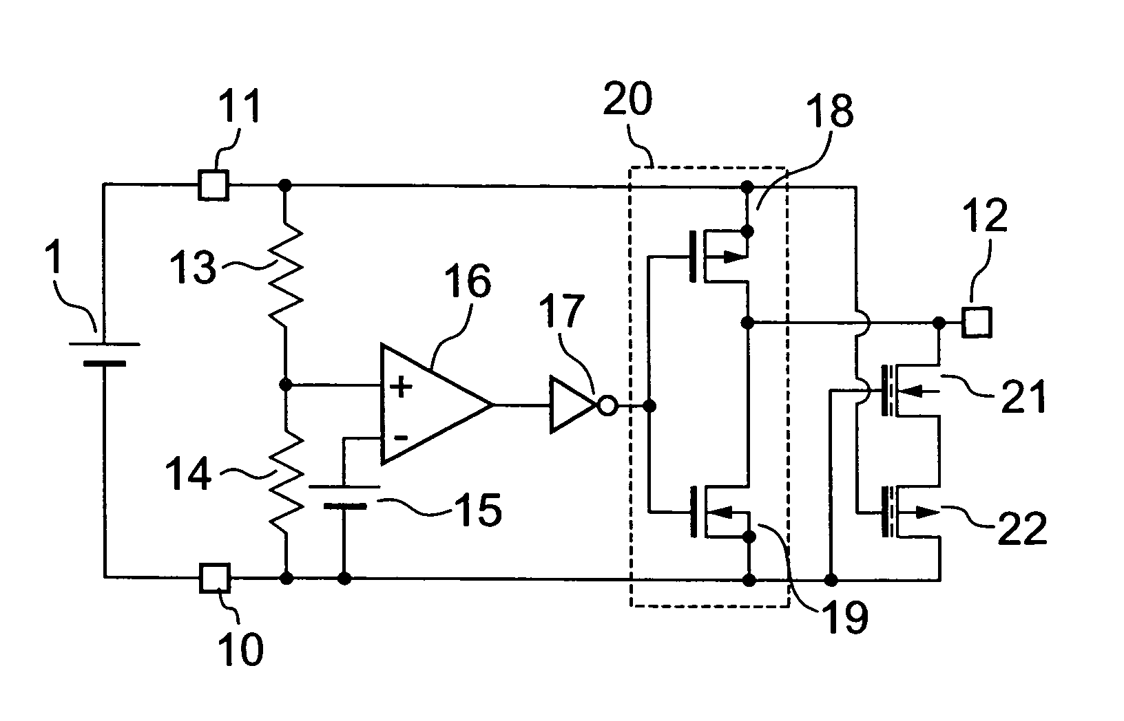
[0027]FIG. 1 is a diagram showing a voltage detecting circuit in accordance with the present invention. A difference between FIGS. 1 and 6 resides in that a depletion-type n-ch MOS Tr 21 and a depletion-type p-ch MOS Tr 22 are connected to an output terminal 12. The basic voltage detection operations are the same as those in the conventional voltage detecting circuit.
[0028]When a voltage V1 across a battery 1 is lower than threshold voltages of enhancement-type MOS Tr 18 and 19, both of the depletion-type n-ch MOS Tr 21 and the depletion-type p-ch MOS Tr 22 turn on with the result that the output of the output terminal 12 becomes L level.
[0029]In this example, when an absolute value of the threshold value of the depletion-type p-ch MOS Tr 22 is made equal to or slightly larger than an absolute value of the threshold value of the enhancement-type n-ch MOS Tr 19, the enhancement-type n-ch MOS Tr 19 can turn on before the voltage across the battery V1 at which the depletion-type p-ch M...
second embodiment
[0035]FIG. 3 shows a voltage detecting circuit in accordance with the present invention. Differences of FIG. 3 from FIG. 1 reside in that the inverter circuit 17 is removed, the output of the comparator 16 is connected to the input of the output circuit 20, and electric elements connected in series to the depletion-type n-ch MOS Tr 21 and the depletion-type p-ch MOS Tr 22 are connected between the output terminal 12 and the terminal 11, that is, to the plus side of the battery 1.
[0036]In addition, in FIG. 3, since there is no inverter 17, the L level and H level of the output terminal 12 are inverted with respect to the voltage across the battery 1 as compared with the case of FIG. 1. That is, the output terminal 12 becomes H in level when the voltage across the battery 1 is the detected voltage or lower, whereas the output terminal 12 becomes L in level when the voltage across the battery 1 is the detected voltage or higher.
[0037]When a voltage V1 across a battery 1 is lower than t...
third embodiment
[0044]FIG. 5 is a diagram showing a voltage detecting circuit in accordance with the present invention. A difference between FIGS. 1 and 5 resides in that a depletion-type n-ch MOS Tr 31 and a depletion-type p-ch MOS Tr 32 are connected to the output of the comparator 16.
[0045]When the voltage of the battery 1 is low and equal to or lower than the operation voltage of the comparator 16, it is not always ensured that the output of the comparator 16 becomes an accurate value. If the voltage across the battery 1 is low and the comparator 16 outputs H level when the output of the comparator 16 must be naturally L level, the inverter circuit 17 outputs L level upon receiving that output, and the output circuit 20 is going to output H level. That is, the enhancement-type p-ch MOS transistor 18 turns on.
[0046]However, because the output terminal 12 is connected with the depletion-type n-ch MOS Tr 21 and the depletion-type p-ch MOS Tr 22, the output terminal 12 is lowered to L level, and a ...
PUM
 Abstract
Description
Claims
Application Information