Expansion cone for radially expanding tubular members
What is AI technical title?
AI technical title is built by Patsnap AI team. It summarizes the technical point description of the patent document.
a tubular member and expansion cone technology, applied in the direction of sealing/packing, furniture parts, borehole/well accessories, etc., can solve the problems of increased drilling rig time, increased cost, and required equipment changes,
Inactive Publication Date: 2006-05-02
SHELL OIL CO
View PDF850 Cites 76 Cited by
Summary
Abstract
Description
Claims
Application Information
AI Technical Summary
This helps you quickly interpret patents by identifying the three key elements:
Problems solved by technology
Method used
Benefits of technology
Benefits of technology
[0011]According to another aspect of the present invention, a tubular member is provided that includes an annular member having a wall thickness that varies less than about 8%, a hoop yield strength that varies less than about 10%, imperfections of less than about 8% of the wall thickness, no failure for radial expansions of up to about 30%, and no necking of the walls of the annular member for radial expansions of up to about 25%.
[0012]According to another aspect of the present invention, a wellbore casing is provided that includes one or more tubular members. Each tubular member includes an annular member having a wall thickness that varies less than about 8%, a hoop yield strength that varies less than about 10%, imperfections of less than about 8% of the wall thickness, no failure for radial expansions of up to about 30%, and no necking of the walls of the annular member for radial expansions of up to about 25%.
[0013]According to another aspect of the present invention, a method of forming a wellbore casing is provided that includes placing a tubular member and an expansion cone in a wellbore and displacing the expansion cone relative to the tubular member. The tubular member includes an annular member having a wall thickness that varies less than about 8%, a hoop yield strength that varies less than about 10%, imperfections of less than about 8% of the wall thickness, no failure for radial expansions of up to about 30%, and no necking of the walls of the annular member for radial expansions of up to about 25%.
Problems solved by technology
Such a large borehole diameter involves increased costs due to heavy casing handling equipment, large drill bits and increased volumes of drilling fluid and drill cuttings.
Moreover, increased drilling rig time is involved due to required cement pumping, cement hardening, required equipment changes due to large variations in hole diameters drilled in the course of the well, and the large volume of cuttings drilled and removed.
The conventional design and construction of wellheads is expensive and complex.
This delays the completion of a well.
Method used
Image
Click on the blue label to locate the original text in one second.
Reading with bidirectional positioning of images and text.
Examples
Embodiment Construction
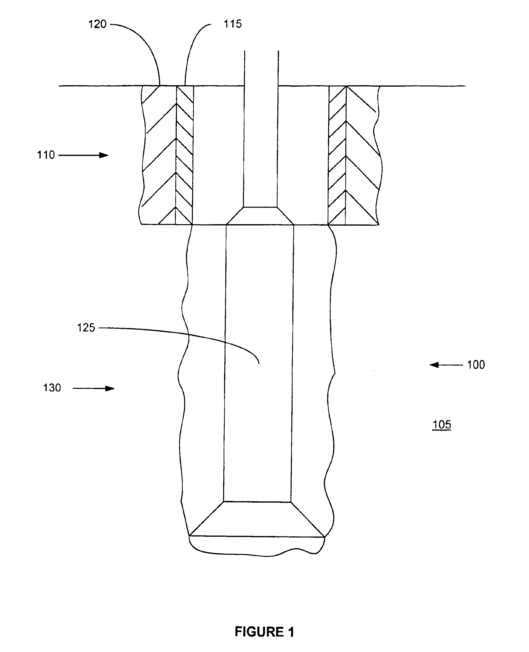
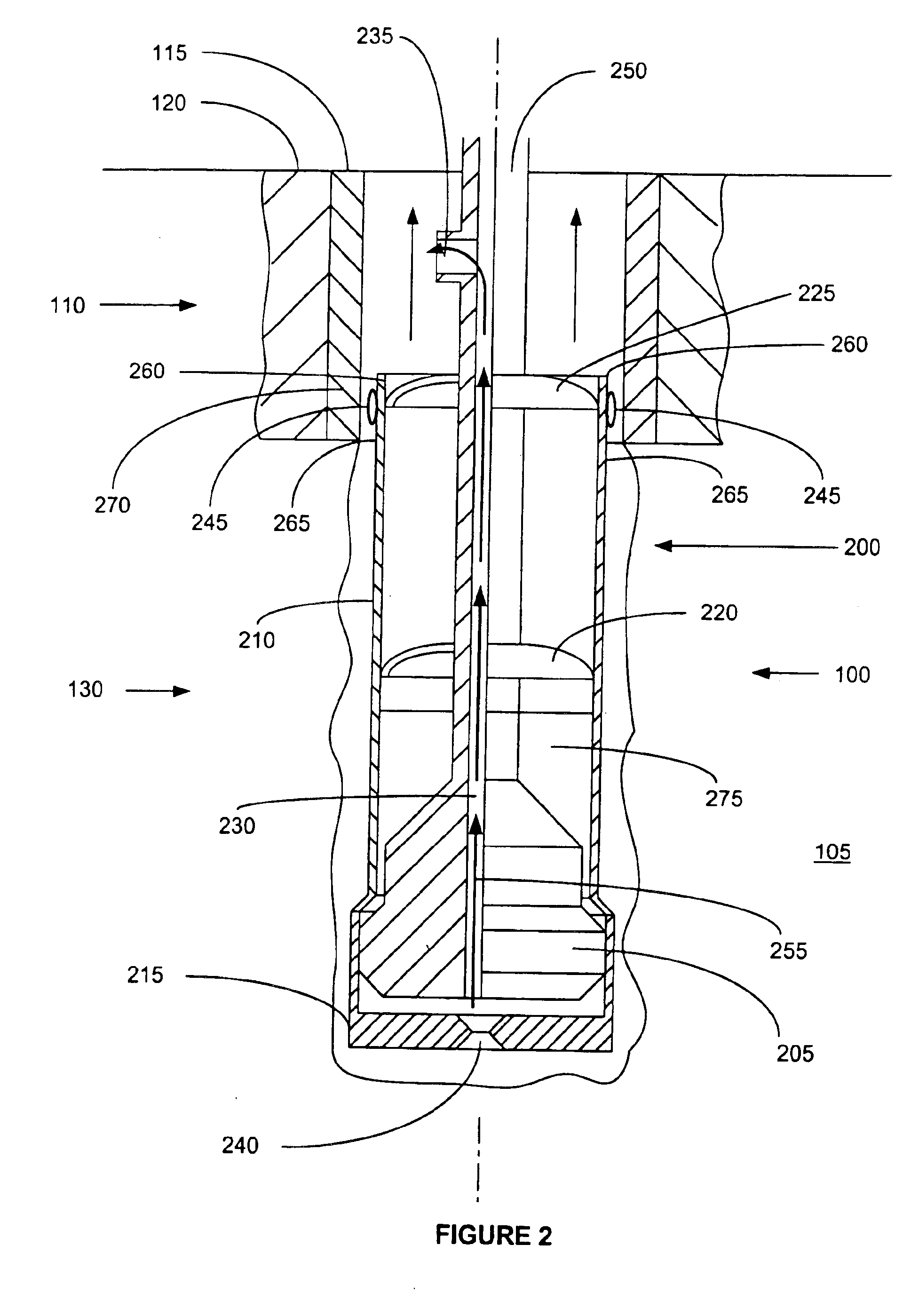
[0099]An apparatus and method for forming a wellbore casing within a subterranean formation is provided. The apparatus and method permits a wellbore casing to be formed in a subterranean formation by placing a tubular member and a mandrel in a new section of a wellbore, and then extruding the tubular member off of the mandrel by pressurizing an interior portion of the tubular member. The apparatus and method further permits adjacent tubular members in the wellbore to be joined using an overlapping joint that prevents fluid and or gas passage. The apparatus and method further permits a new tubular member to be supported by an existing tubular member by expanding the new tubular member into engagement with the existing tubular member. The apparatus and method further minimizes the reduction in the hole size of the wellbore casing necessitated by the addition of new sections of wellbore casing.
[0100]An apparatus and method for forming a tie-back liner using an expandable tubular member...
PUM
Abstract
An expansion cone for radially expanding tubular members.
Description
CROSS REFERENCE TO RELATED APPLICATIONS[0001]This application is a division of U.S. patent application Ser. No. 09 / 588,946, filed Jun. 7, 2000, which issued as U.S. Pat. No. 6,557,640, which claimed the benefit of the filing date of U.S. provisional patent application Ser. No. 60 / 137,998, filed on Jun. 7, 1999, which was a continuation-in-part of U.S. patent application Ser. No. 09 / 559,122, filed Apr. 26, 2000, which issued as U.S. Pat. No. 6,604,763, which claimed the benefit of the filing date of U.S. provisional patent application Ser. No. 60 / 131,106, filed on Apr. 26, 1999, which was a continuation-in-part of U.S. patent application Ser. No. 09 / 523,468, filed Mar. 10, 2000, which issued as U.S. Pat. No. 6,640,903, which claimed the benefit of the filing date of U.S. provisional patent application Ser. No. 60 / 124,042, filed on Mar. 11, 1999, which was a continuation-in-part of U.S. patent application Ser. No. 09 / 510,913, filed Feb. 23, 2000, which claimed the benefit of the filin...
Claims
Application Information
Patent Timeline
Application Date:The date an application was filed.
Publication Date:The date a patent or application was officially published.
First Publication Date:The earliest publication date of a patent with the same application number.
Issue Date:Publication date of the patent grant document.
PCT Entry Date:The Entry date of PCT National Phase.
Estimated Expiry Date:The statutory expiry date of a patent right according to the Patent Law, and it is the longest term of protection that the patent right can achieve without the termination of the patent right due to other reasons(Term extension factor has been taken into account ).
Invalid Date:Actual expiry date is based on effective date or publication date of legal transaction data of invalid patent.

