Leveler interlocking blocks

a technology of interlocking blocks and levelers, which is applied in the direction of lifting devices, inclined ship lifting, construction, etc., can solve the problems of substantial (over 20%) breakage in actual use of interlocking blocks, and achieve the effect of eliminating the inherent breakag

Inactive Publication Date: 2006-05-09
TAI LO YUN
View PDF6 Cites 19 Cited by
  • Summary
  • Abstract
  • Description
  • Claims
  • Application Information

AI Technical Summary

Problems solved by technology

It has been found that this form of interlocking block suffers from substantial (over 20%) breakage in actual use with loaded trucks and recreational vehicles.

Method used


Image

  • Leveler interlocking blocks
  • Leveler interlocking blocks
  • Leveler interlocking blocks

Examples


Embodiment Construction

[0019]The invention is now discussed with reference to the figures

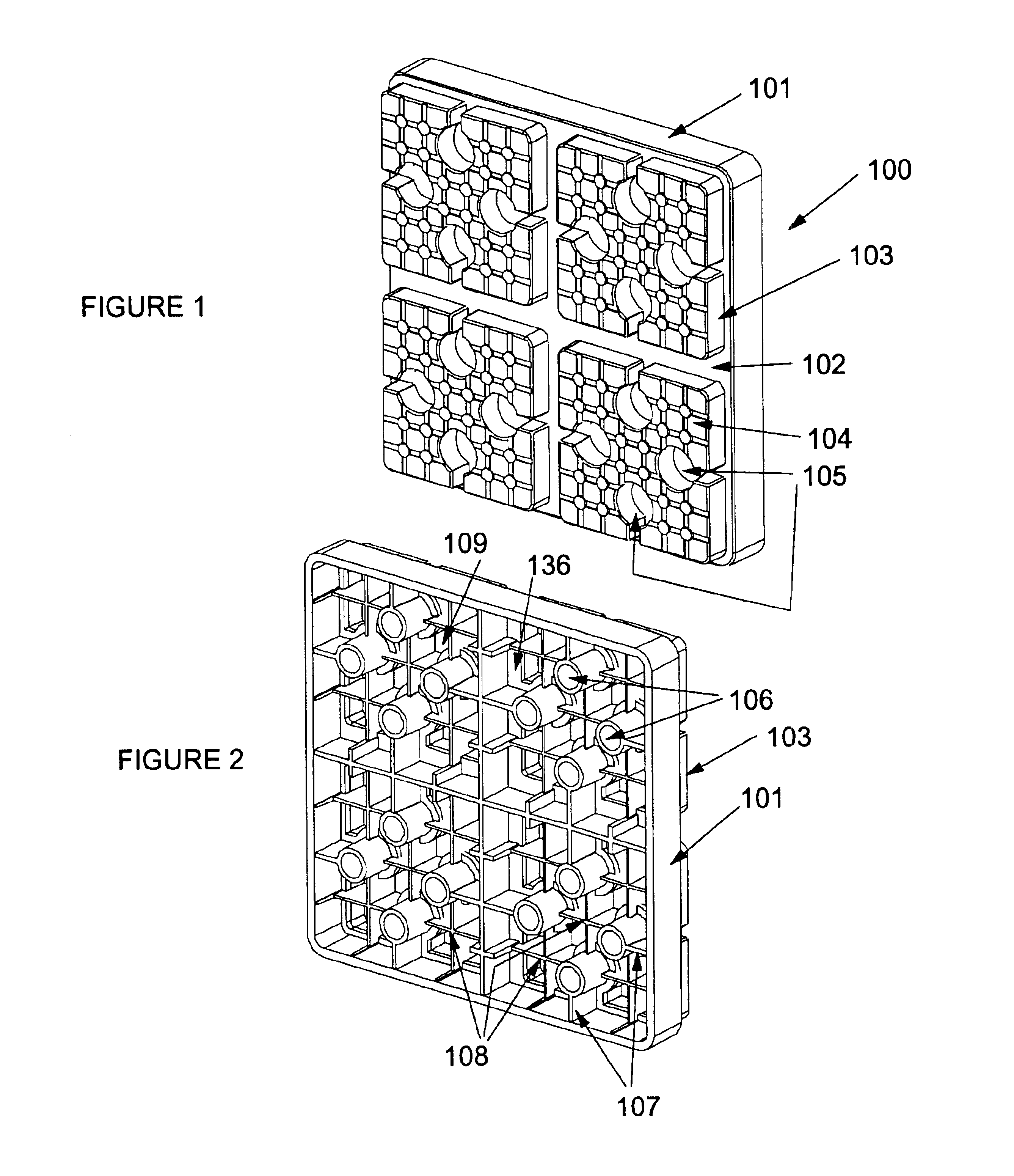
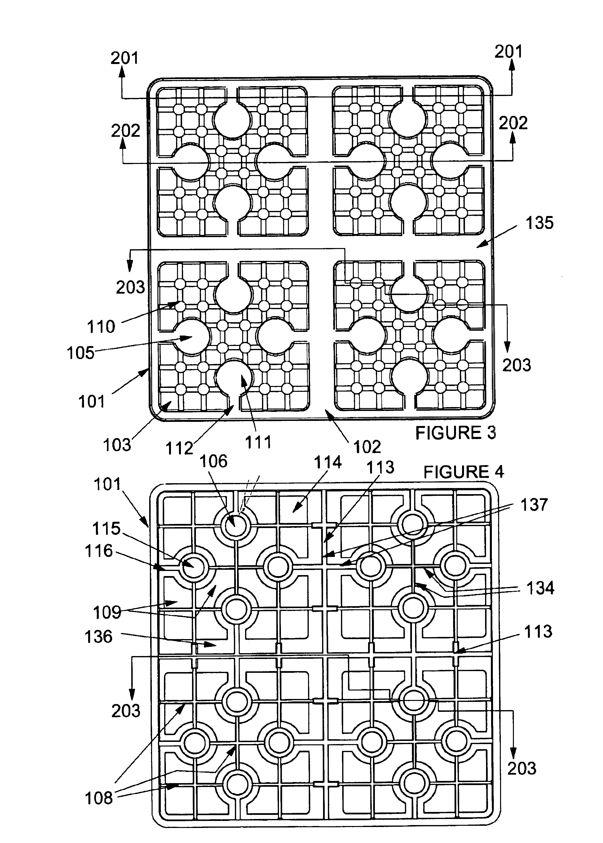
[0020]All of the invention blocks are identical. FIGS. 1 to 4 show front and back views of the invention block 100. Block 100 is square with a main side wall 101 and generally covered across a top of the side wall 101 with a base plate 102 and four identical and substantially square raised parts 103. A side wall 116 (as in FIG. 5) defines the height of raised parts 103 that are in turn covered with a raised part plate 104. Each of the four sides of the square raised parts 103 comprises a key recess 105. The four key recesses each receive a flanged post 106 on the underside of block 100 when one block 100 is interlocked with another block 100 as described below. The underside of block 100 comprises 16 flanged posts 106 connected by an open structure of flanges 107 and 108 extending to different distances from the undersides 136 and 109 respectively of plates 102 and 104. The different distances are adapted to cause und...


PUM


Abstract

The present invention is a set of at least three interlocking blocks where two of the blocks are set on a ground surface and are connected at their top surfaces by a particular configuration of the underside of the third block. Four square and raised parts with four key recesses are formed on the top side of the entirely plastic and unitarily molded block to mate with a cavity and four flanged posts on the underside of another identical block. The critical part of this invention is providing four key recesses in the raised part of the block into which interlock the flanged posts of the underside of the block.

Description

BACKGROUND OF THE INVENTION[0001]The present invention relates to plastic interlocking blocks used to level recreational vehicles and travel trailers.[0002]The prior art describes several forms of interlocking pieces connected so that trucks and recreational vehicles can drive on to them and be leveled at an uneven site. U.S. Pat. No. D426,933 shows one of a set of at least three interlocking blocks that are set up with two side by side and the third placed on top of halves of the bottom two to lock the three together. It has been found that this form of interlocking block suffers from substantial (over 20%) breakage in actual use with loaded trucks and recreational vehicles. The breakage is due to the particular strains placed on the blocks. A tire must be able to drive up a stepped ramp formed by the blocks and then come to rest preferably at the top of the third or top block or at any place on the stepped ramp. The strain that this makes on plastic pieces has been found to be uni...

Claims


Application Information

Patent Timeline
Patent Type & Authority Patents(United States)
IPC IPC(8): E02C3/00
CPCB60P3/36
Inventor TAI, LO YUN
Owner TAI LO YUN
Why Eureka
Try Eureka