Apparatus and methods for providing emergency safety lighting

a technology for emergency safety lighting and apparatus, applied in the field of illumination, can solve problems such as power failure, electrical short circuit, brownout, etc., and achieve the effect of preventing unnecessary power usag

Inactive Publication Date: 2006-05-16
CYBERLUX CORP
View PDF28 Cites 91 Cited by
  • Summary
  • Abstract
  • Description
  • Claims
  • Application Information

AI Technical Summary

Benefits of technology

[0005]The present invention transforms existing electrical wall outlets into an emergency lighting system for homes, hospitals, hotels, nursing homes and businesses. The lighting device, designed as a replacement electrical wall outlet or receptacle, simply plugs into an existing wall outlet. Alternatively, the device may provide a stand-alone unit that replaces a conventional wall outlet receptacle altogether. In either case, the lighting device continues to function as an electrical outlet; however, the device also comprises a local power source such as a constant charge lithium ion battery; a motion sensor for initiating a low level of lighting for transiting a darkened room or corridor; a power sensor for activating a high level of light when electrical service is disrupted, thereby broadcasting a wash of light over an otherwise darkened room or corridor; and a photoelectric cell which detects daylight or otherwise externally provided lighting of a room or corridor thereby preventing unnecessary power usage.

Problems solved by technology

Frequently, homes, offices and industrial plant facilities experience many types of emergency situations involving power failures where an interior or exterior area has no light.
Such power failures may result from electrical short circuits, brownouts, fire, accidents, natural disasters (i.e., floods, hurricanes, tornados, etc.) or a planned shutdown of electricity within a facility or dwelling.
Many facilities, and especially residential homes, do not have emergency generators to provide temporary backup lighting in such situations and thus are limited to nominal emergency lighting in the form of portable light sources, such as flashlights or lanterns.

Method used


Image

  • Apparatus and methods for providing emergency safety lighting
  • Apparatus and methods for providing emergency safety lighting
  • Apparatus and methods for providing emergency safety lighting

Examples


Embodiment Construction

[0014]The present invention now will be described more fully hereinafter with reference to the accompanying drawings, in which preferred embodiments of the invention are shown. This invention may, however, be embodied in many different forms and should not be construed as limited to the embodiments set forth herein; rather, these embodiments are provided so that this disclosure will be thorough and complete and will fully convey the scope of the invention to those skilled in the art. Like numbers refer to like elements throughout.

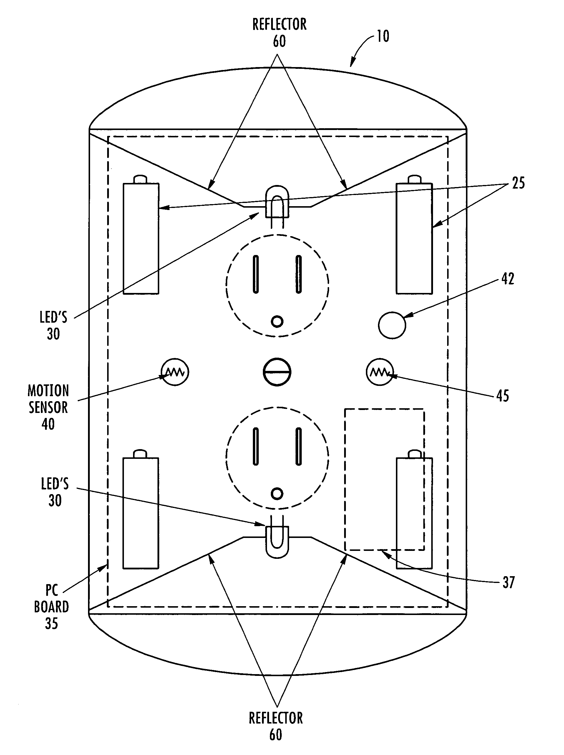
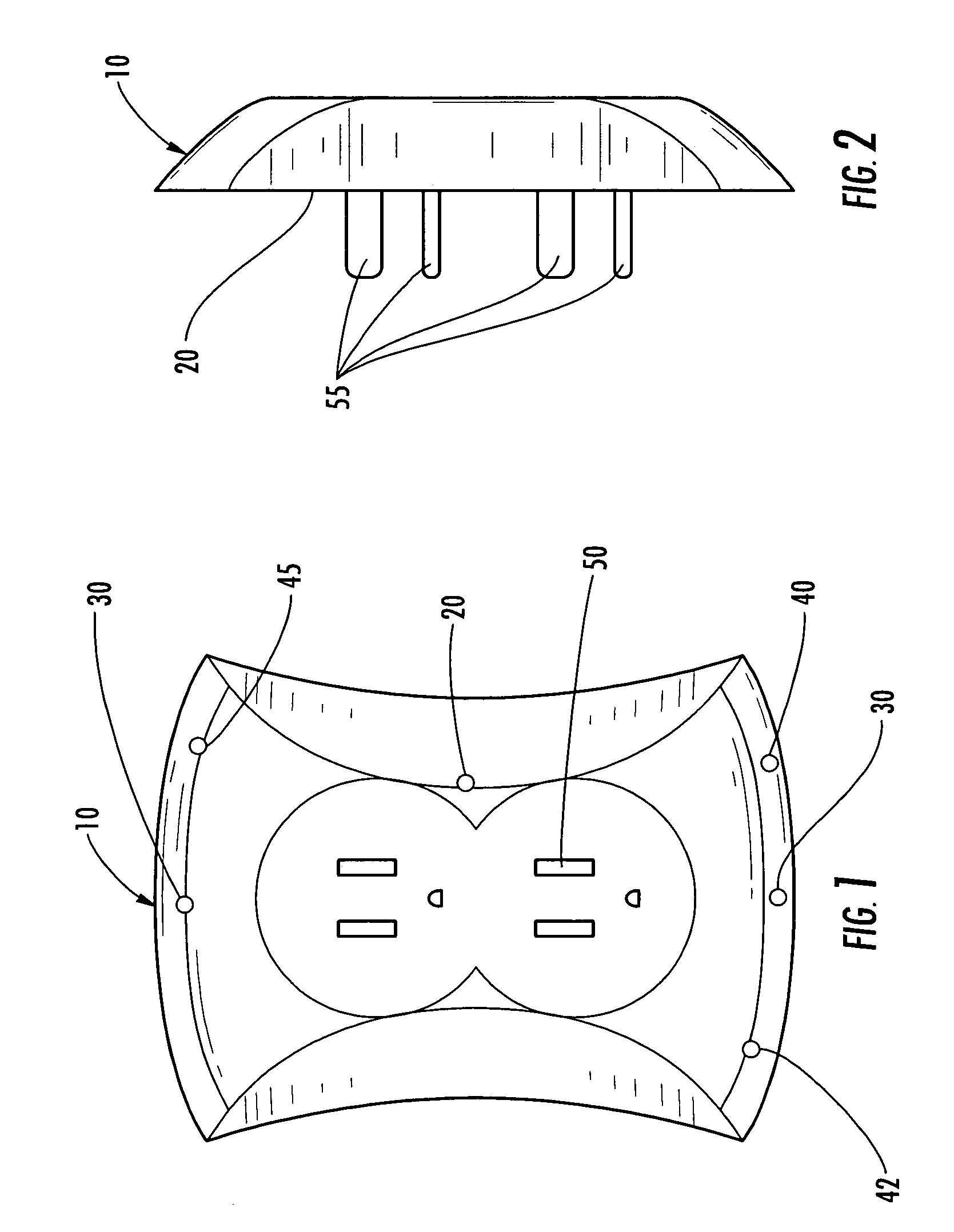
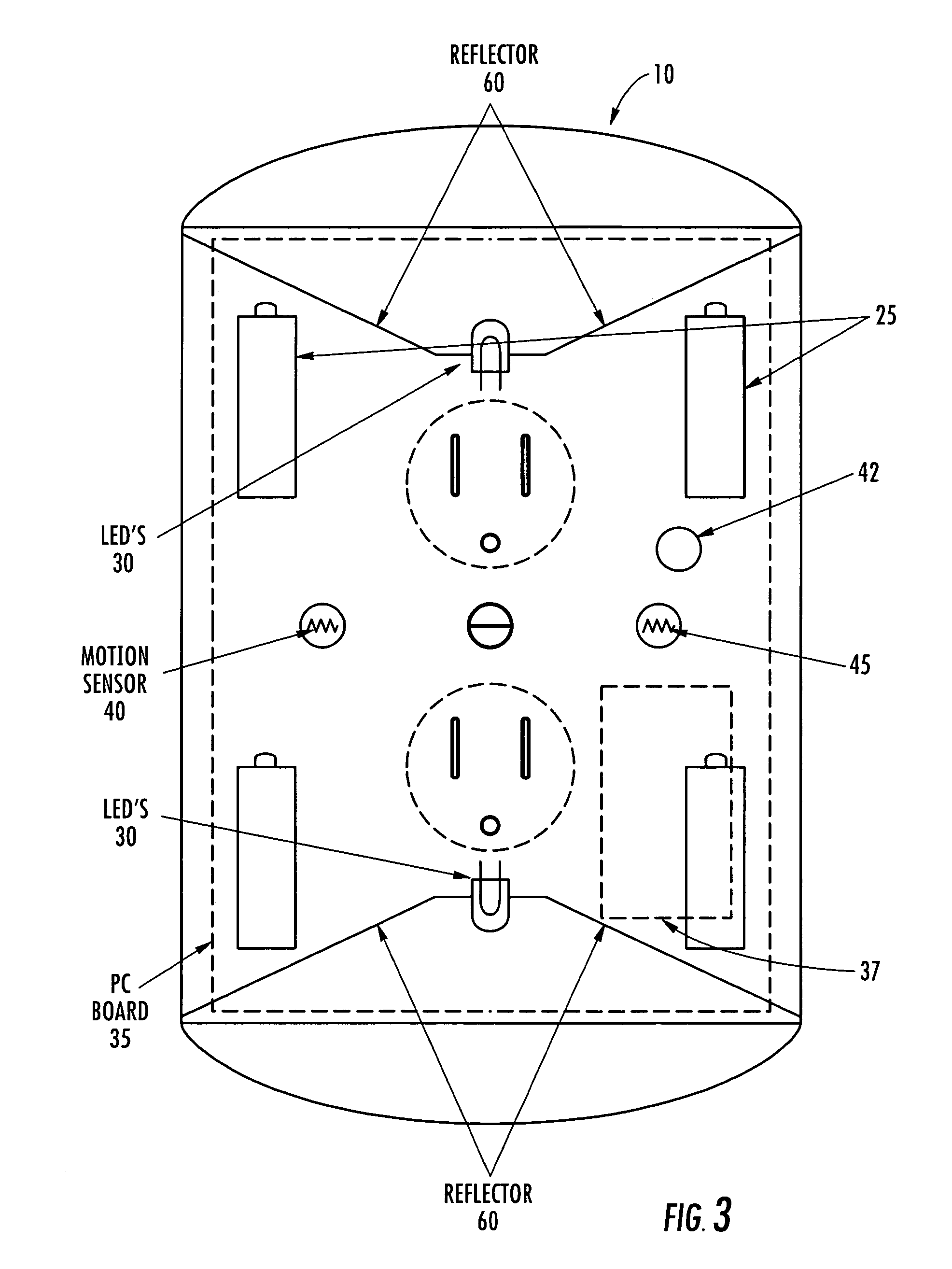
[0015]FIGS. 1 and 2 depict front and side perspectives of a lighting device in accordance with one embodiment of the present invention. According to the depicted embodiment, the lighting device 10 includes a main body housing 20 having a plug-through electrical capability for use in combination with a conventional electrical wall outlet (not shown). In one embodiment, the lighting device 10 is simply plugged into the wall outlet after removal of its facepla...


PUM


Abstract

The present invention transforms existing electrical wall outlets into an emergency lighting system for homes, hospitals, hotels, nursing homes and businesses. The lighting device, designed as a replacement electrical wall outlet or receptacle, simply plugs into an existing dual outlet after removal of its faceplate. The lighting device continues to function as an electrical outlet, however, also comprises a local power source such as a constant charge lithium ion battery; a motion sensor for initiating a low level of lighting for darkened room or corridor transit; a power sensor for activating a high level of light when electrical service is disrupted, thereby broadcasting a wash of light over an otherwise darkened room or corridor; and a photoelectric cell which detects daylight or otherwise provided lighting of the room or corridor and thereby prevent unnecessary power usage.

Description

CROSS-REFERENCE TO RELATED APPLICATIONS[0001]The present application claims priority to U.S. Provisional Application. No. 60 / 510,915 filed Oct. 14, 2003; the contents of which are incorporated herein in their entirety.FIELD OF THE INVENTION[0002]The present invention relates generally to the field of illumination and, more particularly, the invention relates to a solid state lighting source such as a light-emitting diode (LED) device that provides for multi-level, motion sensitive illumination in emergency situations.BACKGROUND OF THE INVENTION[0003]Frequently, homes, offices and industrial plant facilities experience many types of emergency situations involving power failures where an interior or exterior area has no light. Such power failures may result from electrical short circuits, brownouts, fire, accidents, natural disasters (i.e., floods, hurricanes, tornados, etc.) or a planned shutdown of electricity within a facility or dwelling. Many facilities, and especially residentia...

Claims


Application Information

Patent Timeline
Patent Type & Authority Patents(United States)
IPC IPC(8): F21V33/00F21S8/00F21S9/02F21V23/04H01R13/66H01R13/717H01R25/00H02J9/02
CPCF21S8/035F21S9/022F21V23/04F21V23/0442H01R13/6683H01R13/717H01R13/7175H02J9/02H01R25/006F21Y2101/02F21Y2115/10
Inventor EVANS, DONALD F.
Owner CYBERLUX CORP
Why Eureka
Try Eureka