Distributed computing component system with diagrammatic graphical representation of code with separate delineated display area by type
What is AI technical title?
AI technical title is built by Patsnap AI team. It summarizes the technical point description of the patent document.
a distributed computing and component technology, applied in the field of data processing systems, can solve the problems of significant programming development time and cost savings of conventional tools, and software development tools also save significant programming development time and cos
Inactive Publication Date: 2006-05-23
BORLAND
View PDF10 Cites 222 Cited by
Summary
Abstract
Description
Claims
Application Information
AI Technical Summary
This helps you quickly interpret patents by identifying the three key elements:
Problems solved by technology
Method used
Benefits of technology
Benefits of technology
[0035]The software development tool also saves significant programming development time as well as costs for conventional tools by allowing a developer to generate, compile, assemble, deploy, and debug a distributed computing component, such as an Enterprise JavaBean™, without having to use multiple conventional tools. By using the software development tool to support and deploy an EJB, a developer produces error-free code in a shorter amount of time as the risk of error is reduced by alleviating the need to switch from tool to tool during the development and deployment process of the EJB. In addition, the software development tool provides the programmer with a segregated grouping and view of methods that define the behavior of an EJB, where the programmer is able to easily identify a method in an EJB implementation class to a respective method signature in either an EJB Home Interface or an EJB Remote Interface that corresponds to the EJB implementation class as explained below.
Problems solved by technology
The software development tool also saves significant programming development time as well as costs for conventional tools by allowing a developer to generate, compile, assemble, deploy, and debug a distributed computing component, such as an Enterprise JavaBean™, without having to use multiple conventional tools.
Method used
Image
Click on the blue label to locate the original text in one second.
Reading with bidirectional positioning of images and text.
Examples
Embodiment Construction
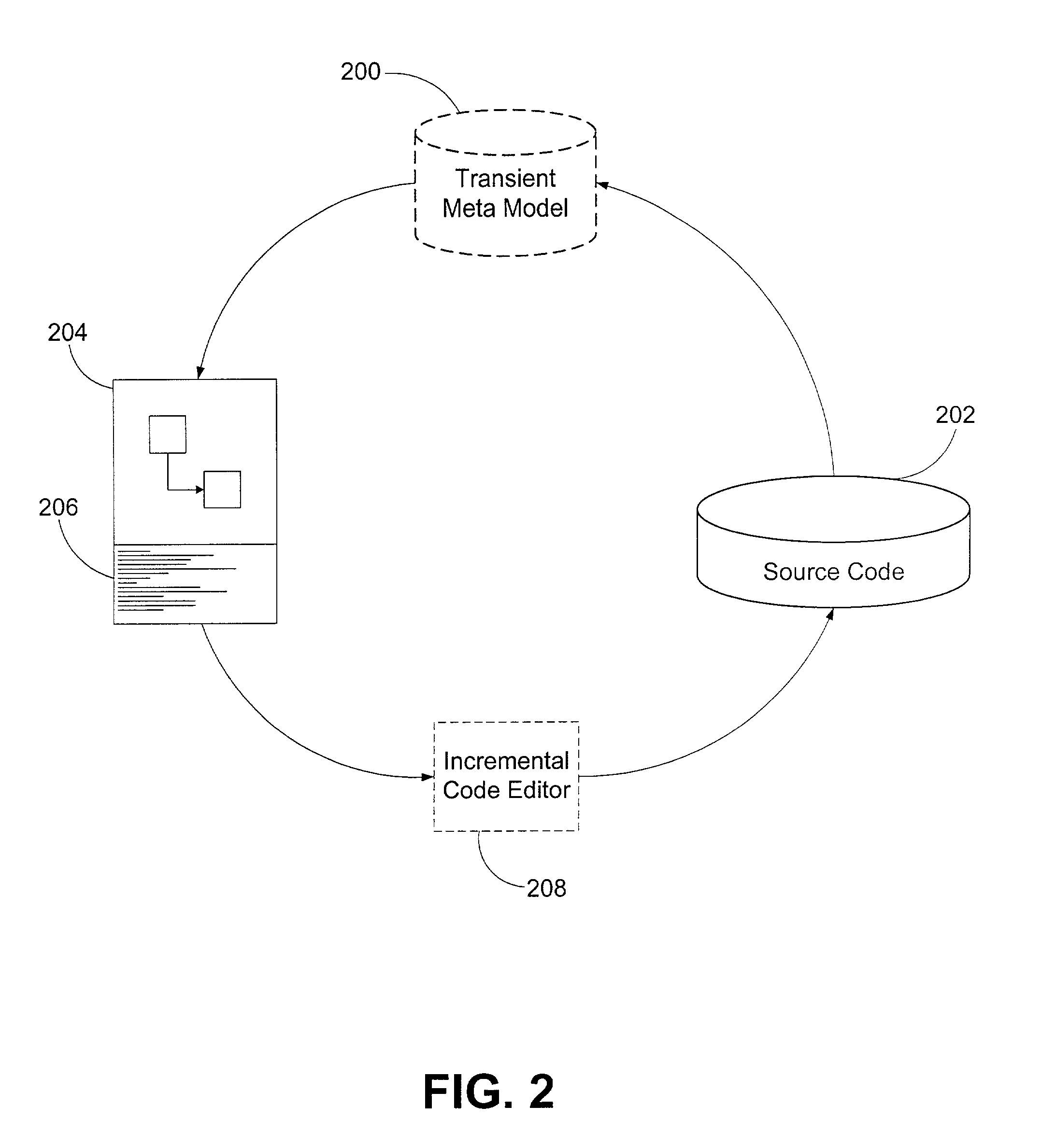
[0112]Methods and systems consistent with the present invention provide an improved software development tool that creates a graphical representation of source code regardless of the programming language in which the code is written. In addition, the software development tool simultaneously reflects any modifications to the source code to both the display of the graphical representation as well as the textual display of the source code.
[0113]As depicted in FIG. 2, source code 202 is being displayed in both a graphical form 204 and a textual form 206. In accordance with methods and systems consistent with the present invention, the improved software development tool generates a transient meta model (TMM) 200 which stores a language-neutral representation of the source code 202. The graphical 204 and textual 206 representations of the source code 202 are generated from the language-neutral representation in the TMM 200. Alternatively, the textual view 206 of the source code may be obt...
PUM
Abstract
Methods and systems consistent with the present invention provide an improved software development tool that generates code corresponding to a distributed computing component that contains methods of a plurality of types and that displays a graphical representation of the code with a separately delineated display area for each type. The improved software development tool also compiles, deploys, and debugs the distributed computing component with a client software component using methods and systems consistent with the present invention.
Description
RELATED APPLICATIONS[0001]This application claims the benefit of the filing date of U.S. Provisional Application No. 60 / 199,046, entitled “Software Development Tool,” filed on Apr. 21, 2000, and is a continuation-in-part of U.S. patent application Ser. No. 09 / 680,063, entitled “Method and System for Developing Software,” filed on Oct. 4, 2000, now U.S. Pat. No. 6,851,107, which claims the benefit of the filing date of U.S. Provisional Application No. 60 / 157,826, entitled “Visual Unified Modeling Language Development Tool,” filed on Oct. 5, 1999, and U.S. Provisional Application No. 60 / 199,046, entitled “Software Development Tool,” filed on Apr. 21, 2000; all of which are incorporated herein by reference.[0002]The following identified U.S. patent applications are also relied upon and are incorporated by reference in this application:[0003]U.S. patent application Ser. No. 09 / 680,065, entitled “Method And System For Displaying Changes Of Source Code,” filed on Oct. 4, 2000;[0004]U.S. p...
Claims
Application Information
Patent Timeline
Application Date:The date an application was filed.
Publication Date:The date a patent or application was officially published.
First Publication Date:The earliest publication date of a patent with the same application number.
Issue Date:Publication date of the patent grant document.
PCT Entry Date:The Entry date of PCT National Phase.
Estimated Expiry Date:The statutory expiry date of a patent right according to the Patent Law, and it is the longest term of protection that the patent right can achieve without the termination of the patent right due to other reasons(Term extension factor has been taken into account ).
Invalid Date:Actual expiry date is based on effective date or publication date of legal transaction data of invalid patent.

