Suction-adhesive device

a technology of suction and adhesive, which is applied in the direction of shaving accessories, machine supports, other domestic objects, etc., can solve the problems of air entering, device being detached, and falling to the floor, and achieve the effect of improving the suction-adhesive devi

Active Publication Date: 2006-06-27
GOLDEN PEAK PLASTIC WORKS
View PDF6 Cites 72 Cited by
  • Summary
  • Abstract
  • Description
  • Claims
  • Application Information

AI Technical Summary

Benefits of technology

[0004]It is an object of the present invention to overcome or substantially ameliorate th

Problems solved by technology

Sooner or later however, air enters into the space between the cup and th

Method used


Image

  • Suction-adhesive device
  • Suction-adhesive device
  • Suction-adhesive device

Examples


Embodiment Construction

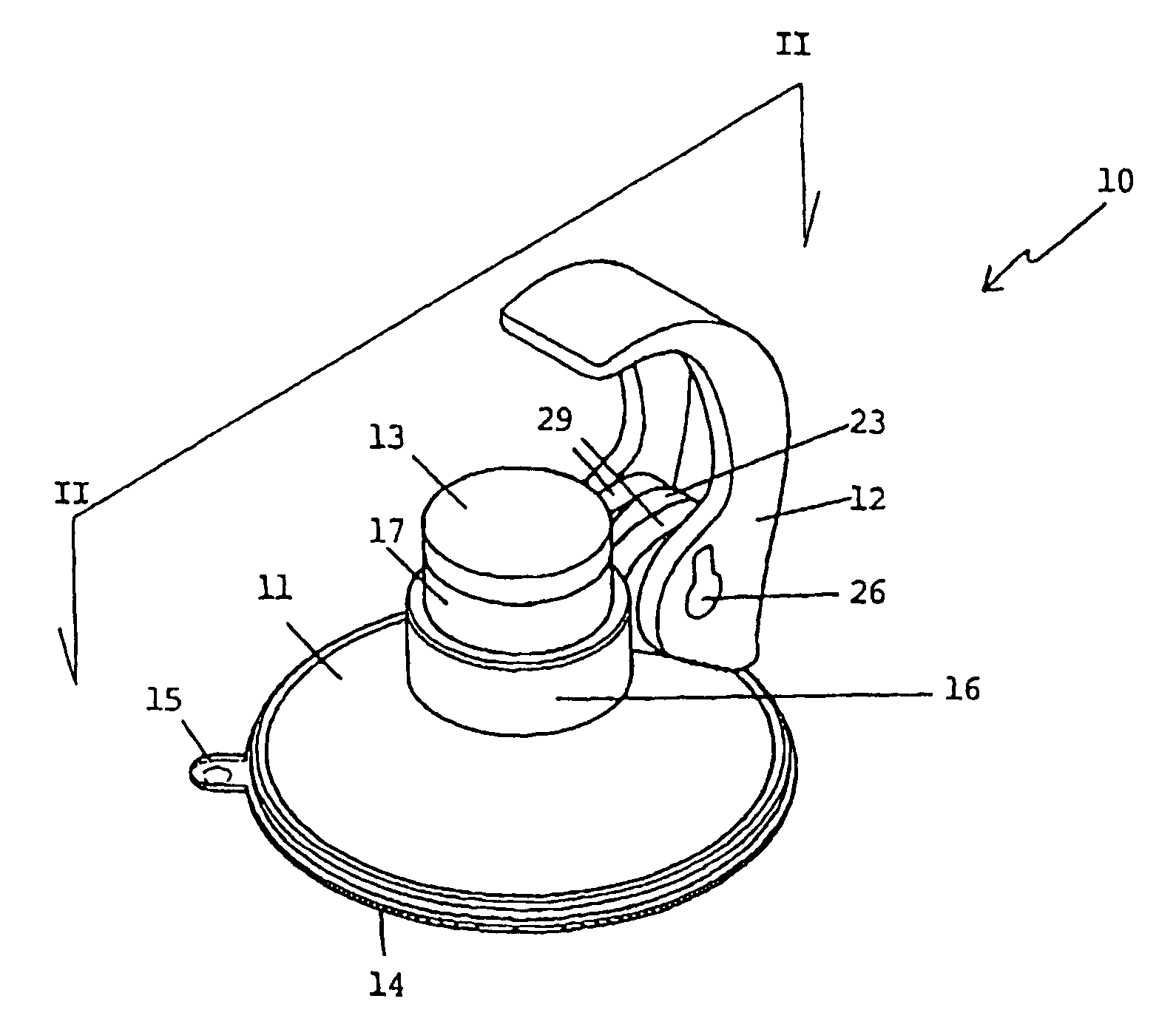
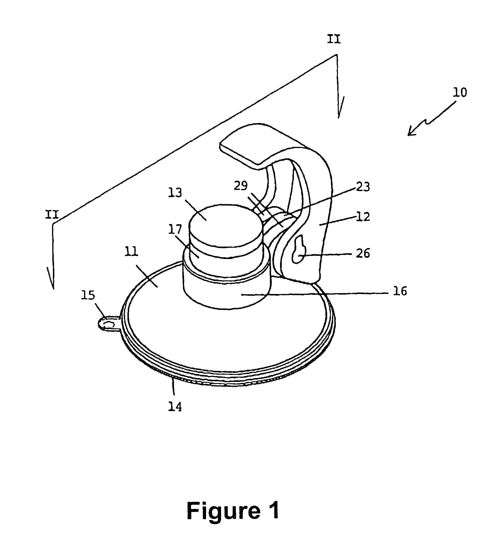
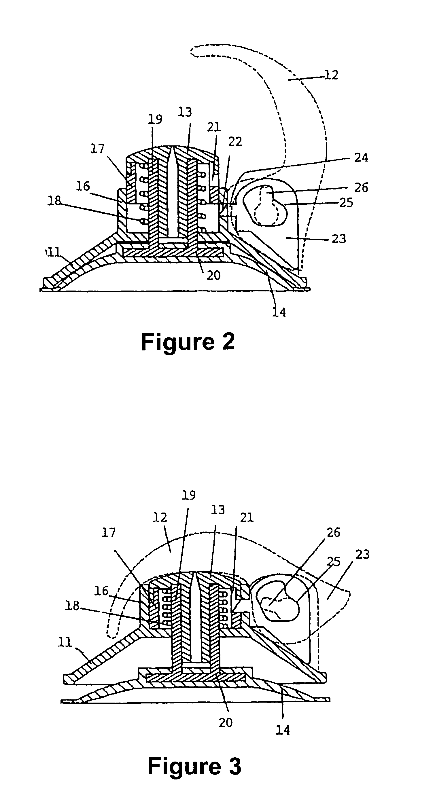
[0026]In FIGS. 1 to 5 of the accompanying drawings, there is schematically depicted a suction-adhesive device 10. The device 10 comprises a body 11 typically moulded from rigid plastics material. The body 11 includes a neck 16 through which a stem 19 extends. At the top of the stem 19 there is provided a pushbutton 13.

[0027]A coil spring 18 is situated beneath the pushbutton 13 and surrounds an upper portion of the stem 19. The bottom end of the compression spring 18 bears downwardly on the body 11 to bias the stem 19 upwardly.

[0028]Surrounding an upper portion of the compression spring 19 and affixed with respect to the pushbutton 13 is a coloured ring 17. The ring 17 has a contrasting colour compared with that of the body 11 or its neck 16 and is preferably in red colour, and can be glued or otherwise adhered to the downwardly projecting annular lip of the pushbutton 13.

[0029]The stem 19 has at its bottom a flange 20 to which there is attached a suction cup 14. Suction cup 14 is m...


PUM


Abstract

A suction-adhesive device comprising a suction cup, a stem extending from the suction cup, and a body through which the stem extends. A spring interacts with the stem and the body for biasing the suction cup towards the body to apply suction. A coloured ring is fixed on the stem for indicating when the spring has drawn the suction cup towards the body.

Description

BACKGROUND OF THE INVENTION[0001]The present invention relates to a suction-adhesive device. More particularly, although not exclusively, the invention relates to a device including a suction cup and a hook, typically for attachment to a bathroom wall tile, window or shower screen and from which articles such as a face washer, corded soap, a shower cap or other articles may be suspended.[0002]It is known to use suction cup devices for securing items to a bathroom wall tile for example. Small soap dishes for example can comprise two such suction cups. The suction cups usually comprise a bulbous protrusion in the centre that passes through an aperture in the side of the soap dish. It is also known to provide suction cups with a hook from which items can be suspended. The hook may be integrally moulded with the cup or formed of a lessflexible material and attached to the cup.[0003]The above and other known suction cup devices tend to hold more securely to a surface if the face of the s...

Claims


Application Information

Patent Timeline
IPC IPC(8): A45D42/14F16B47/00
CPCF16B47/006A47K2201/00
Inventor KWOK, CHIN-PANG
Owner GOLDEN PEAK PLASTIC WORKS
Why Eureka
Try Eureka