Antenna arrangement and method relating thereto

a technology of antenna arrangement and antenna arrangement, applied in diversity/multi-antenna system, beacon system using radio waves, instruments, etc., can solve the problems of excessive losses of transmitted and received signals in the system, complicated situation, and duplex filtering, so as to reduce the loss of transmitted and/or received signals and reduce the loss of downlink combiners

Inactive Publication Date: 2006-06-27
TELEFON AB LM ERICSSON (PUBL)
View PDF6 Cites 29 Cited by
  • Summary
  • Abstract
  • Description
  • Claims
  • Application Information

AI Technical Summary

Benefits of technology

[0013]What is needed is therefore an antenna arrangement which provides for diversity and in which the losses for transmitted and/or received signals are low. Particularly an antenna arrangement is needed which does not require bulky and expensive filters. Still further an antenna arrangement is needed through which the losses produced through downlink combiners can be reduced as compared to hitherto known arrangements. Particularly an antenna arrangement is needed which allows a large num

Problems solved by technology

Radio propagation is strongly affected by the terrain or the landscape, and irregularities therein, and in a city, the situation gets complicated due to buildings, constructions etc. and the base station antenna arrangements often have to be arranged quite close to each other.
The installation of base station antenna arrangements also gets complicated due to a number of factors in addition to the pure technical factors in that there is a general requirement that the installations be more or less aesthetical in the cities as well as on the countryside.
Also for Radio in the Local Loop installations; wireless LAN:s (Local Area Networks), i.e. both indoor and outdoor installations, there are complications.
It is a disadvantage of such systems that the duplex filters introduce excessive losses to the transmitted and received signals in the system.
Such filters are both expensive and demand a lot of volume.
Such a solution will, however, result in additional costs for feeding networks and

Method used


Image

  • Antenna arrangement and method relating thereto
  • Antenna arrangement and method relating thereto
  • Antenna arrangement and method relating thereto

Examples


Embodiment Construction

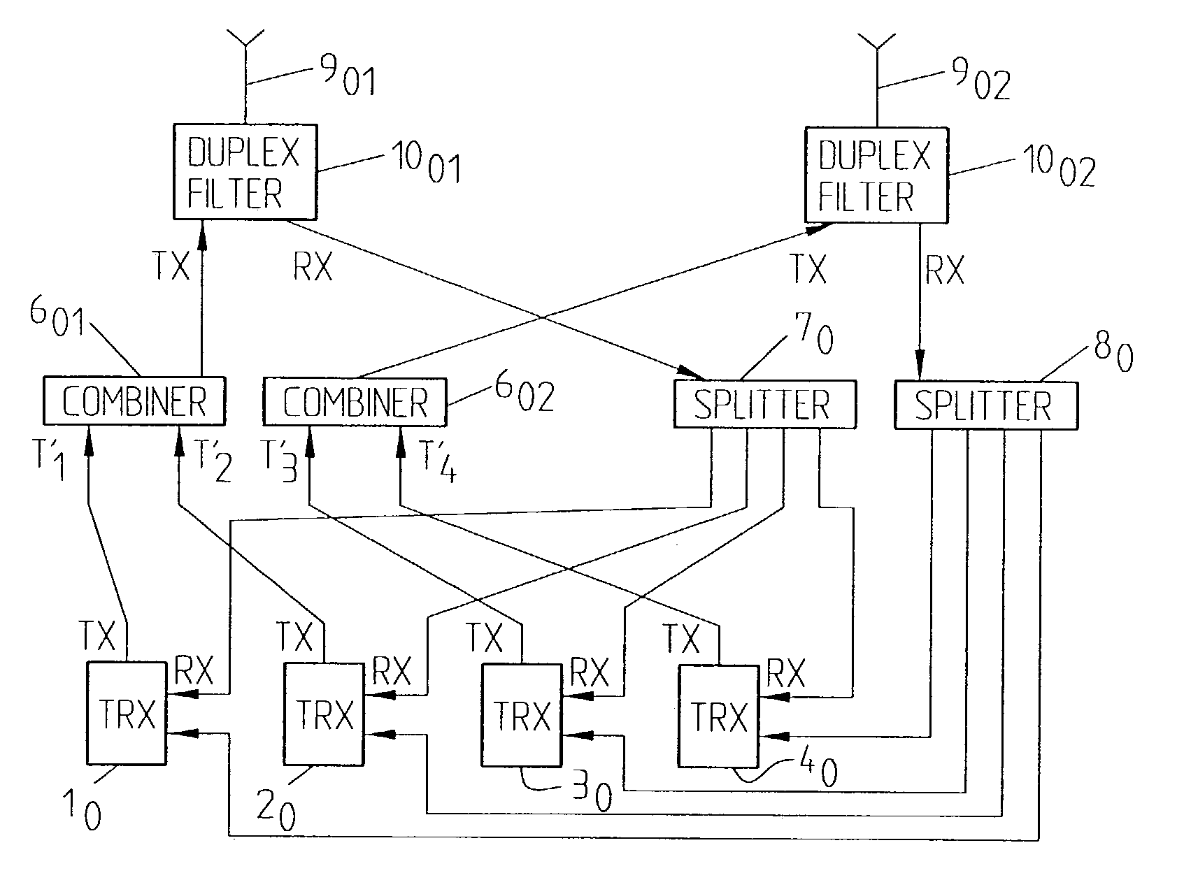
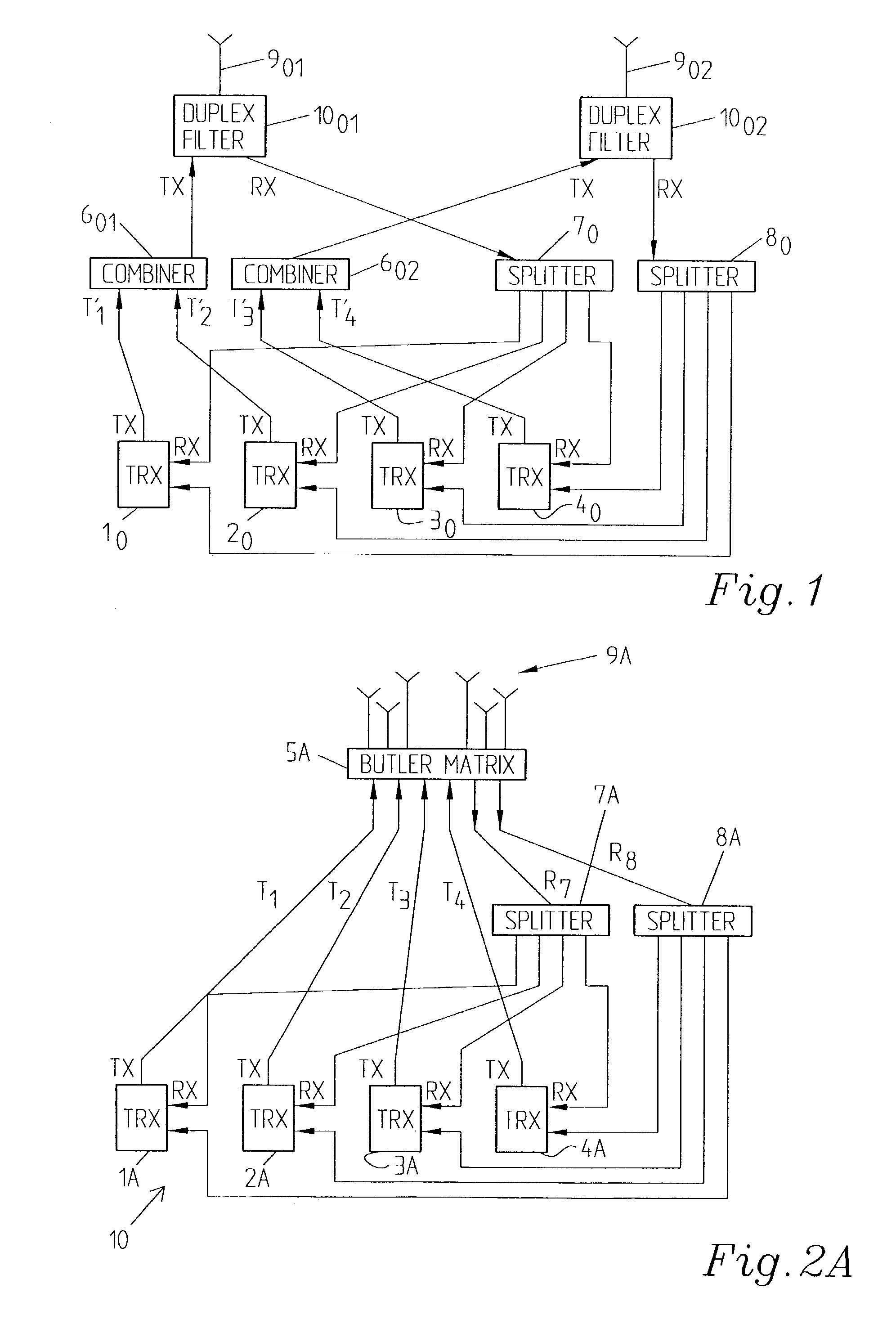
[0046]In the block diagram of FIG. 1 a conventional, omni-directional base station antenna arrangement with four transceivers TRX 10, 20, 30, 40 is disclosed. The illustrated device employs space diversity. A duplex filter 1001, 1002 is connected to each antenna 901, 902. For downlink communication, the signals from TRX 10, 20 are combined in combining means 601 whereas the signals T3′, T4′ from TRXs 30, 40 are combined in combining means 602. The combined signals T1′, T2′ are provided to duplex filter 1001 and then output to antenna means 901. In a similar manner signals T3′, T4′ are combined in combining means 602, output to duplex filter 1002 and provided to antenna means 902. As referred to earlier in the application, the downlink combining means 601, 602 introduce very high losses and for an arrangement containing more transceivers, the losses on the downlink will indeed be severe.

[0047]For uplink communication, signals received in the antenna means 901, 902 are input to the re...


PUM


Abstract

The present invention relates to an omnidirectional base station antenna arrangement with a number of antenna elements and a number of transceiver means for transmitting and receiving signals to/from a number of user stations. A feeding network is provided which comprises a number of phase ports, a number of which form first phase ports connected to a number of transceiver means for downlink communication and a number of which form second phase ports connected to a number of transceiver means for uplink communication. The feeding network comprises a number of antenna ports connected to antenna elements and the feeding network generates substantially independent, orthogonal signals to provide for phase diversity and the antenna elements are arranged to form at least one cylindrical array antenna. The invention also relates to a method of providing communication between an omnidirectional base station antenna arrangement with a number of antenna elements and a number of transceiver means and a number of user stations as well as to a method of providing for at least phase diversity transmission at an omnidirectional base station antenna arrangement.

Description

[0001]This application is a continuation of international application PCT / SEO1 / 01266 filed 7 Jun. 2001 which designates the U.S.TECHNICAL FIELD[0002]The present invention relates to a base station antenna arrangement with a number of antenna elements and a number of transceiver means for communication with user stations. The invention also relates to a method of providing communication between a base station antenna arrangement comprising a number of antenna elements and a number of transceiver means, and a number of user stations. Particularly the invention also relates to a method of providing at least phase diversity transmission at a base station antenna arrangement.STATE OF THE ART[0003]Cellular (mobile) telecommunication systems and other wireless (cellular or non-cellular; mobile or non-mobile) communication systems normally require a considerable number of base station antenna arrangements. They need to be provided all over the area that is to be covered by the cellular comm...

Claims


Application Information

Patent Timeline
IPC IPC(8): H04Q7/20H04B7/00H01Q1/24H01Q3/40H04B7/04
CPCH01Q1/246H04B7/0491H01Q3/40
Inventor JOHANNISSON, BJORNDERNERYD, ANDERSJOSEFSSON, LARS
Owner TELEFON AB LM ERICSSON (PUBL)
Why Eureka
Try Eureka