Card edge connector with latching arms

a technology of latching arms and card edges, which is applied in the direction of coupling device connection, coupling parts engagement/disengagement, electrical apparatus, etc., can solve the problems of deformation of latching arms, unfavorable electrical connection between circuit cards and connectors, and inability to find them easily

Active Publication Date: 2006-07-11
HON HAI PRECISION IND CO LTD
View PDF8 Cites 43 Cited by
  • Summary
  • Abstract
  • Description
  • Claims
  • Application Information

AI Technical Summary

Benefits of technology

[0007]Accordingly, an object of the present invention is to provide a card edge connector which allows accurate accommodation and holding of card modules within the connector, and which can insure stable holding of card module therein.

Problems solved by technology

This connector suffers from a problem that concerns the reliability of the accommodation and holding of the circuit board in a correct place.
Accordingly, the connector is held with in the connector by the projection portions of the latching arms, awful electrical connection between the circuit card and the connector which can not be found easily is be established, even, there is a danger that the latching arms will be deformed.

Method used


Image

  • Card edge connector with latching arms
  • Card edge connector with latching arms
  • Card edge connector with latching arms

Examples


Embodiment Construction

[0016]Reference will now be made in detail to the preferred embodiment of the present invention.

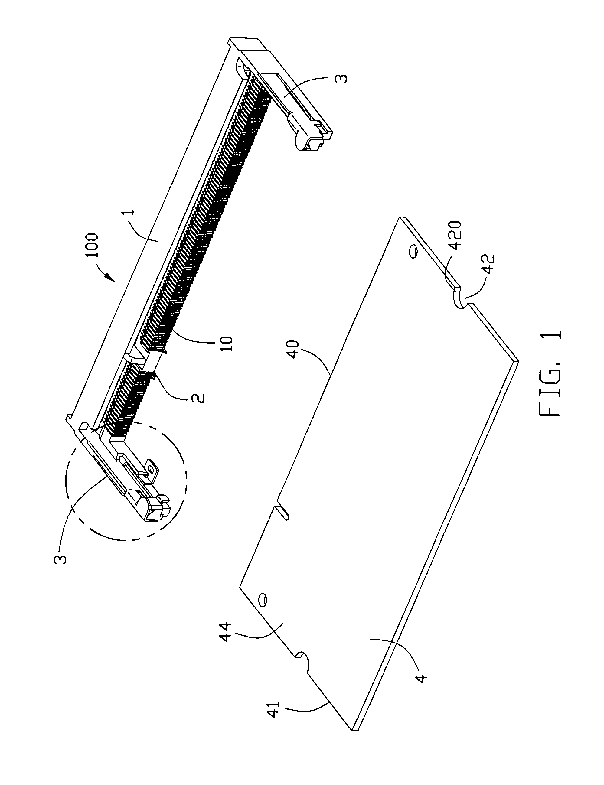
[0017]FIG. 1 shows a card edge connector 100 in accordance with the present invention for accommodating a card module 4 in a determined plane. Incidentally, the card module 4 is card-shaped and has a plurality of conductive pads (not shown is FIGS.) on top and bottom surfaces 44, 43 at an edge 40 and a pair of notch 42 at two opposite side edges 41. The card edge connector 100 comprises an insulative housing 1 and a plurality of contacts 2 received in the insulative housing 1.

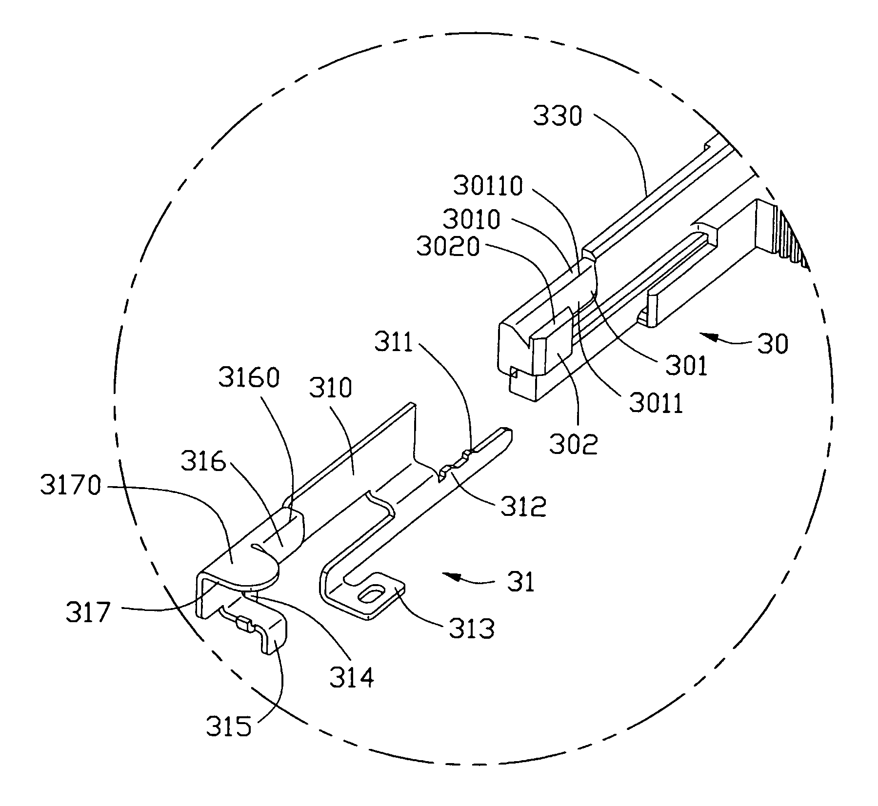
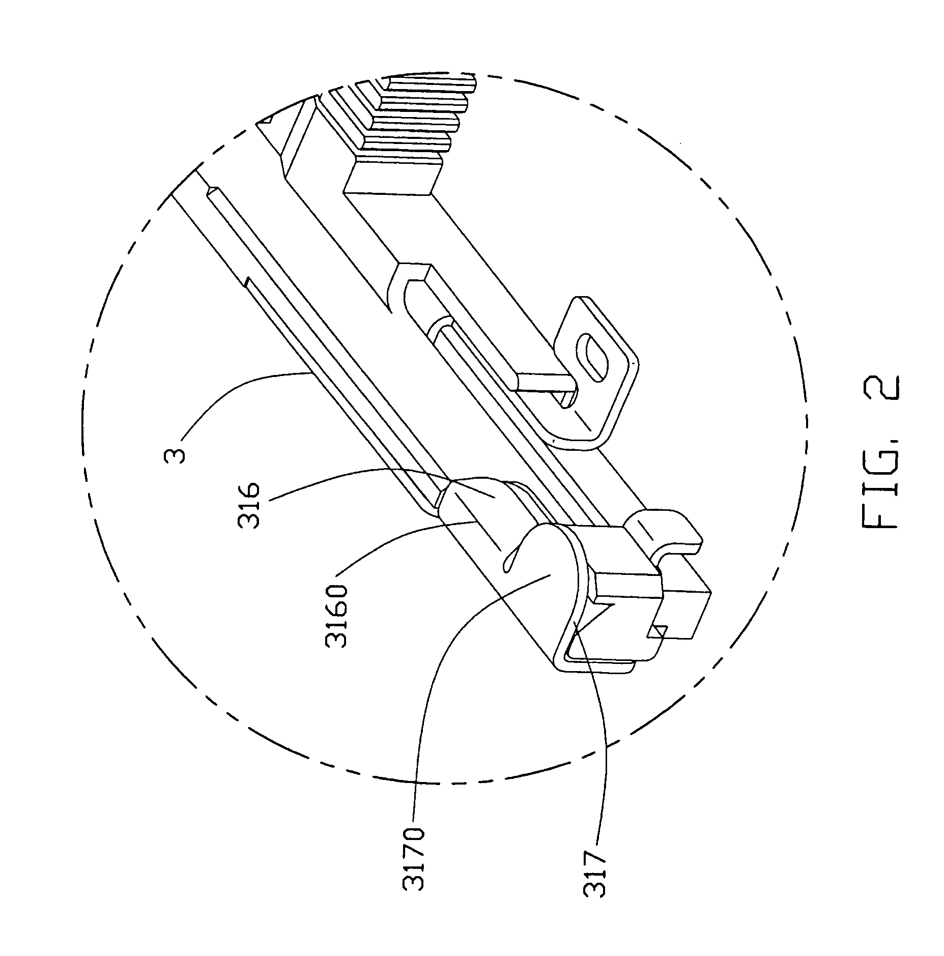
[0018]With reference to FIGS. 1–4, the insulative housing 1 has a base defining a central slot 10 along an elongated direction therein. The contacts 2 are disposed by two sides of the central slot 10 for respectively electrical engaging with conductive pads of the card module 4. The central slot 10 accommodates the edge 40 of the card module 4 as shown in FIGS. 5–6. Two latching arms 3 extend forwardly in a cantileve...


PUM


Abstract

A card edge connector (100) comprises an insulative housing (1) defining a central slot (10) with a plurality of contacts (2) by two sides. Two arms (3) are positioned at two opposite ends of the insulative housing. Each arm includes a plastic portion (30) and a metal portion (31) attached to the plastic potion. The plastic portion includes a locking lug (301) and a restraint head (302). The metal portion is retained to the housing and extends inwardly a guidance stud (316) and a stop tag (317) for covering the locking lug and the restraint head respectively, and the stop tag is as high as an upper end of the guidance stud. While a card module is inserted into the central slot in a correct position and rotated downwardly to directly engage and push the guidance studs, the metal portions together with the plastic portions can be deflected outwards so that the card module is secured held.

Description

BACKGROUND OF THE INVENTION[0001]1. Field of the Invention[0002]The invention relates to electrical connectors, and particularly to a card edge connector with latching arms thereof for retaining a card module therein.[0003]2. Description of Related Art[0004]Primarily as a result of the expansion of memory in the computer field, techniques have become known is which semiconductor devices containing memories are mounted on card modules. In most cases, card edge connectors are used for the connection of such card modules to circuit boards. Card edge connectors have a substantially C-shaped configuration in which a pair of arms are formed in positions on both end portions of an insulating housing main body which carries numerous contacts.[0005]One example of a latch-equipped electrical connector is disclosed in U.S. Pat. No. 5,779,494. The connector accommodates memory circuit card which has recesses located in the side edges. Two latching arms are integrally formed with a housing along...

Claims


Application Information

Patent Timeline
Patent Type & Authority Patents(United States)
IPC IPC(8): H01R13/625
CPCH01R12/83H01R12/7005H01R12/7011
Inventor YANG, XIANG-QIYANG, XIAO-GAOLI, REN-CHIH
Owner HON HAI PRECISION IND CO LTD
Why Eureka
Try Eureka