Lithographic apparatus and device manufacturing method

a technology of lithographic apparatus and manufacturing method, which is applied in the direction of electrical apparatus, printers, instruments, etc., can solve the problems of absorption, diffraction and refraction, adverse effects on illumination quality, and unsatisfactory effects, so as to achieve the effect of destroying the electrostatic field above the channel and effectively causing a shielding

Active Publication Date: 2006-08-08
ASML NETHERLANDS BV
View PDF17 Cites 19 Cited by
  • Summary
  • Abstract
  • Description
  • Claims
  • Application Information

AI Technical Summary

Benefits of technology

[0011]One aspect of the invention provides a lithographic apparatus wherein the recessed channel comprises a shielding layer for shielding the channel structure from the electrostatic field. Thus, breakthrough in the channel is effectively prevented. Beneficially, the shielding layer prevents or at least diminishes an effective attractive electrostatic field to be developed above the channel. Although effectively reducing an overall applied clamping force, especially the absence of clamping pressure above the channel is profitable, since due to an effective support in that area, the applied clamping pressure results in unwanted deformation of the article, which contributes negatively to image resolution of the lithographic apparatus.

Problems solved by technology

In lithographic processing, passing of the beam through gas compositions present between the illumination system and the articles to be illuminated, in particular non-homogenous gas compositions, may cause undesired effects such as absorption, diffraction and refraction.
These effects may have an adverse effect on illumination quality, in particular on a resolution to be reached for the ever increasing demand in imaging performance.
This vacuum technology offers challenges in terms of temperature control.
In the vacuum pressure ranges that are used, thermal conductivity is substantially proportional to the pressure, which means that the thermal energy absorbed by the article when placed in the beam can no longer adequately be diverted, so that unwanted thermal heating of the article supports, leading to thermal expansion and resulting projection inaccuracies or potentially to even the loss of the article.
This provides a substantial risk of voltage breakthrough in the gas feed region.
Especially in non-vacuum conditions, breakthrough is likely to occur when the clamp is turned on.
Although effectively reducing an overall applied clamping force, especially the absence of clamping pressure above the channel is profitable, since due to an effective support in that area, the applied clamping pressure results in unwanted deformation of the article, which contributes negatively to image resolution of the lithographic apparatus.

Method used


Image

  • Lithographic apparatus and device manufacturing method
  • Lithographic apparatus and device manufacturing method
  • Lithographic apparatus and device manufacturing method

Examples


Embodiment Construction

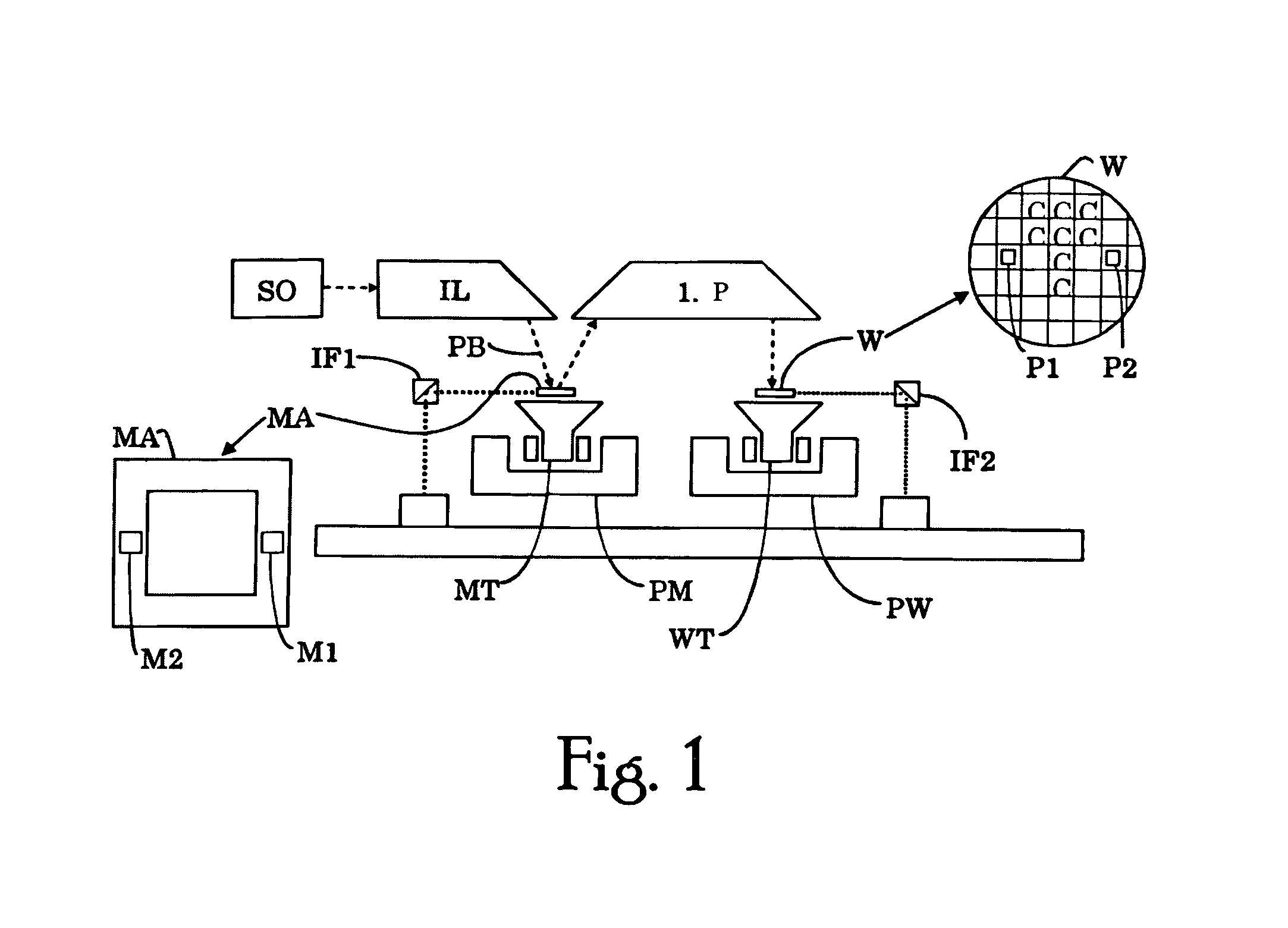
[0030]FIG. 1 schematically depicts a lithographic apparatus according to an embodiment of the invention. The apparatus comprises: an illumination system (illuminator) IL for providing a beam PB of radiation (e.g. UV or EUV radiation); a first support (e.g. a mask table) MT for supporting patterning device (e.g. a mask) MA and connected to first positioning device PM for accurately positioning the patterning device with respect to a projection system (“lens”) PL; a substrate table (e.g. a wafer table) WT for holding a substrate (e.g. a resist-coated wafer) W and connected to second positioning device PW for accurately positioning the substrate with respect to the projection system PL; and the projection system (e.g. a reflective projection lens) PL for imaging a pattern imparted to the beam PB by patterning device MA onto a target portion C (e.g. comprising one or more dies) of the substrate W.

[0031]As here depicted, the apparatus is of a reflective type (e.g. employing a reflective ...


PUM

PropertyMeasurementUnit
diameteraaaaaaaaaa
diameteraaaaaaaaaa
wavelengthaaaaaaaaaa

Abstract

A lithographic apparatus includes an illumination system for providing a beam of radiation, an article support for supporting a flat article to be placed in a beam path of the beam of radiation on the article support, an electrostatic clamp for clamping the article against the article support by an electrostatic field during projection, and a recessed backfill gas feed arranged in the article support for feeding backfill gas to a backside of the article when supported by the article support. According to one aspect of the invention, the recessed backfill gas feed includes a shielding layer for shielding the backfill gas in the recessed backfill gas feed from the electrostatic field.

Description

BACKGROUND OF THE INVENTION[0001]1. Field of the Invention[0002]The present invention relates to a lithographic apparatus, an article support, and a device manufacturing method.[0003]2. Brief Description of Related Art[0004]A lithographic apparatus is a machine that applies a desired pattern onto a target portion of a substrate. Lithographic apparatus can be used, for example, in the manufacture of integrated circuits (ICs). In that circumstance, a patterning device, such as a mask, may be used to generate a circuit pattern corresponding to an individual layer of the IC, and this pattern can be imaged onto a target portion (e.g. comprising part of, one or several dies) on a substrate (e.g. a silicon wafer) that has a layer of radiation-sensitive material (resist). In general, a single substrate will contain a network of adjacent target portions that are successively exposed. Known lithographic apparatus include so-called steppers, in which each target portion is irradiated by exposi...

Claims


Application Information

Patent Timeline
Patent Type & Authority Patents(United States)
IPC IPC(8): G03B27/62G03B27/58H02N13/00G03F7/20H01L21/027H01L21/683
CPCG03F7/707H01L21/6831G03F7/70875
Inventor OTTENS, JOOST JEROENMOORS, JOHANNES HUBERTUS JOSEPHINAGIESEN, PETER THEODORUS MARIA
Owner ASML NETHERLANDS BV
Why Eureka
Try Eureka