
Conveyor system with distributed article manipulation

a distribution system and conveyor technology, applied in the field of conveyors, can solve the problems of unfavorable article exiting the singulator, batch type manipulation process may not be as fast, and not all items are manipulated

Active Publication Date: 2006-08-15
KÖRBER SUPPLY CHAIN LLC
View PDF54 Cites 48 Cited by
  • Summary
  • Abstract
  • Description
  • Claims
  • Application Information

AI Technical Summary

Benefits of technology

The present invention provides an efficient and effective way for maneuvering objects without causing any noise or vibration. This technology can be used in small spaces and offers advantages over existing methods such as reduced costs and improved performance.

Problems solved by technology

The patent text describes a problem in the field of conveyor systems, where articles are often not arranged in a way that is conducive to being transported and processed by the conveyor system. The text describes several existing methods for manipulating articles to a single file line, but each has its disadvantages such as uneven flow of articles or inefficient use of floor space. The technical problem is to provide an improved singulator that overcomes these disadvantages and can better manipulate articles into a single file line.

Method used


Image

  • Conveyor system with distributed article manipulation
  • Conveyor system with distributed article manipulation
  • Conveyor system with distributed article manipulation

Examples


Embodiment Construction

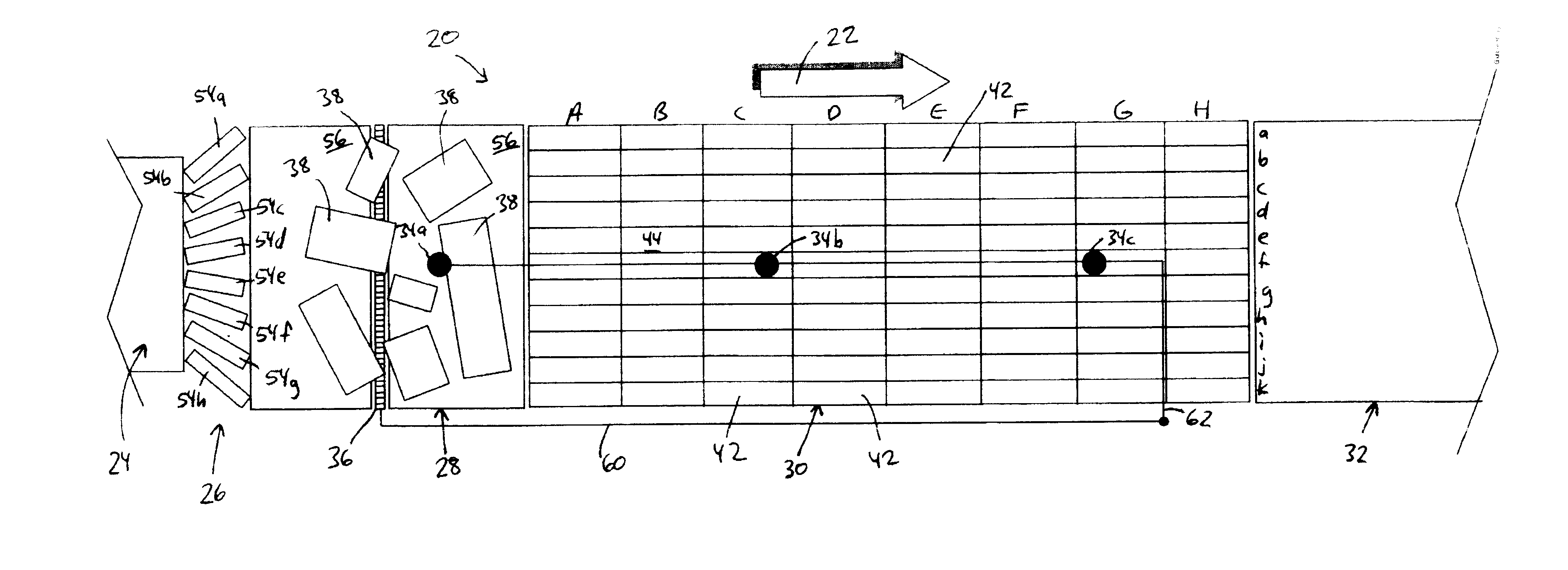
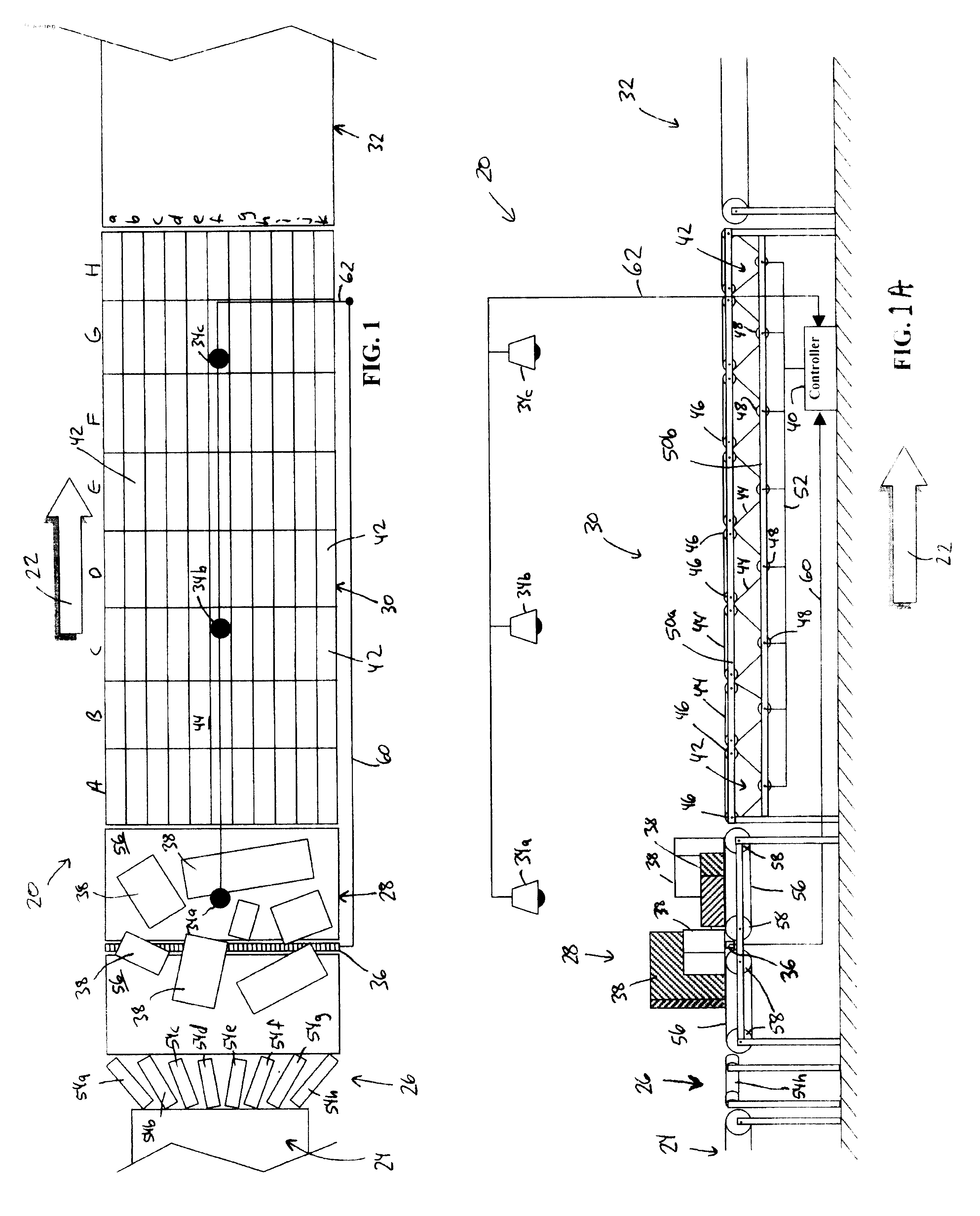
[0037]The present invention will now be described with reference to the accompanying drawings wherein the reference numerals in the following written description correspond to like-numbered elements in the accompanying drawings. An article manipulation system 20 according to a first embodiment of the present invention is depicted in FIGS. 1 and 1A. Article manipulation system 20 moves articles in a direction of conveyance indicated by arrow 22. Article manipulation system 20 includes a feed conveyor 24, a gapper 26, a transition conveyor 28, a distributed manipulation bed 30, and a downstream conveyor 32. Article manipulation system 20 further includes one or more article sensors. In the illustrated embodiment, a plurality of video cameras 34 and a photo sensor array 36 are used. However, other configurations of article sensors may be used. By way of example, a plurality of parallel photo sensor arrays 36 may be spaced along manipulation bed 30 between groups of individual conveyors...


PUM


Abstract

A system and method for manipulating articles includes providing a bed having at least one conveying surface. The conveying surface is adapted to move articles in a direction of conveyance from an upstream end to a downstream end of the bed. At least one sensor is provided to determine the position of any articles on the bed. Selected articles are moved in the direction of conveyance at a speed that is generally higher than articles traveling on the bed that have yet to be manipulated and the articles are selectively rotated.

Description


Claims


Application Information

Patent Timeline
Owner KÖRBER SUPPLY CHAIN LLC
Features
  • Generate Ideas
  • Intellectual Property
  • Life Sciences
  • Materials
  • Tech Scout
  • Unparalleled Data Quality
  • Higher Quality Content
  • 60% Fewer Hallucinations
Learn More