Apparatus and method for two stage ejection of a molded preform from a mold

a technology of injection molding and preforms, which is applied in the field of methods and apparatus for injection molding preforms, can solve the problems of mold closure, mold deformation, and irregular sealing surface portion, and achieve the effect of reducing surface structure, quick and efficient removal of molded plastic preforms, and minimizing deformation of preforms

Inactive Publication Date: 2006-10-31
HUSKY INJECTION MOLDING SYST LTD
View PDF24 Cites 70 Cited by
  • Summary
  • Abstract
  • Description
  • Claims
  • Application Information

AI Technical Summary

Benefits of technology

[0024]An advantage of the present invention is the provision of methods and apparatus for quickly and efficiently removing molded plastic preforms from the molds, while minimizing deformation to the preforms.
[0025]According to a first aspect of the present invention, structure and / or steps are provided for a lock ring for use in an injection mold, including an inner sidewall surface having an area for sealing and aligning with a complementary surface on a mold core. An upper surface is provided having an area for sealing and aligning with a complementary surface on a neck ring, and having a lifting surface for lifting a lower portion of a molded article. The lock ring is configured to lift a preform from the mold core during a first lifting operation, and configured to separate from the neck ring during a second lifting operation.
[0026]According to a second aspect of the present invention, structure and / or steps are provided for an ejection apparatus, including a lock ring having an inner surface with an area for sealing and aligning with a complementary surface on a core. The lock ring also has an upper surface with an area for sealing and aligning with a complementary surface on a neck ring. The upper surface includes a lifting structure for lifting a portion of a molded article. Also included is a neck ring having a contoured inner surface, wherein said neck ring comprises at least two neck ring portions. The lock ring of the ejection apparatus is configured to lift a molded article from the core during a first lifting operation, and configured to separate from the neck ring during a second lifting operation by the neck ring.
[0027]According to a third aspect of the present invention, structure and / or steps are provided for a plastic preform injection molding machine in which a mold cavity is configured to receive a molten material and form it into a molded plastic preform, and a mold core is configured to engage an interior surface of the molded plastic preform. A first lifting structure has an inner surface with an area for sealing and aligning with a complementary surface on a core, and has an upper surface with an area for sealing and aligning with a complementary surface on a second lifting structure. The upper surface of the first lifting structure is configured to lift a molded plastic preform from the injection mold in a lifting direction for a first period of time, where the lower portion of the molded plastic preform lies in a plane substantially perpendicular to the lifting direction. A second lifting structure has an inner surface configured to lift an outer surface of the molded plastic preform from the injection mold in the lifting direction for a second period of time, where the outer surface of the molded plastic preform lies in a plane substantially parallel to the lifting direction.
[0028]According to a fourth aspect of the present invention, a structure and / or steps are provided for ejecting a preform from an injection mold, including an injection mold core having structure complementary to an inner surface of a lock ring, and a lock ring having an inner surface structure for sealing and aligning with the core. The lock ring has an upper surface structure complementary to a lower surface on a neck ring, and the upper surface structure includes a lifting structure for lifting a portion of a molded article. A neck ring has a lower surface structure for sealing and aligning with the lock ring, and having a contoured inner surface. The lock ring is configured to be translated with respect to the injection mold core during a first translation, and the neck ring is configured to be translated with respect to the lock ring during a second translation, in order to remove the molded article from the injection mold.
[0029]According to a fifth aspect of the present invention, structure and / or steps are provided for an injection mold assembly, wherein a cavity insert is provided in a cavity plate. An injection mold core including structure complementary to an inner surface of a lock ring is also provided. The lock ring has an inner surface structure for sealing and aligning with the core, as well as an upper surface structure complementary to a lower surface on a neck ring. The upper surface structure of the lock ring includes a lifting structure for lifting a portion of a molded article. Further provided is a neck ring with a lower surface structure for sealing and aligning with the lock ring, the neck ring being mounted on movable slides. The injection mold assembly also includes a core plate, an ejector plate, and a stripper plate that supports the movable slides.

Problems solved by technology

The time needed to injection-mold the preform is typically limited by the time needed to cool and solidify injected polymer material sufficiently to permit removal of the part from the mold without causing deformation or distortion.
If the polymer material has not sufficiently solidified throughout the neck-finish wall cross-section, the neck-finish will not have sufficient strength to transmit the force and thus can deform and distort during removal, causing the sealing surface portion to become irregular and incapable of maintaining proper seal with the closure.
In addition to the distortion problem described above, another problem with known mold designs is where the neck ring halves do not seal against the core when they are closed (assembled), and the mold is then closed and clamped.
However, this design is not optimal because if there is a gap between these two cylindrical surfaces greater than about 0.001 inch, the risk of plastic leaking through this gap during injection is significant.
Unfortunately, molds wear as they are used, and eventually a design like this leaks.
However, this design was not optimal because the preform still had neck-ring distortions when it was stripped from the core.
However, this design suffered from two disadvantages.
First the small area of contact between the neck ring and the top sealing surface still required substantial cooling time to prevent neck ring distortions.
Second, this design had the cylindrical neck ring mating surfaces which allowed for leakage of the molten plastic.

Method used


Image

  • Apparatus and method for two stage ejection of a molded preform from a mold
  • Apparatus and method for two stage ejection of a molded preform from a mold
  • Apparatus and method for two stage ejection of a molded preform from a mold

Examples


Embodiment Construction

1. Introduction

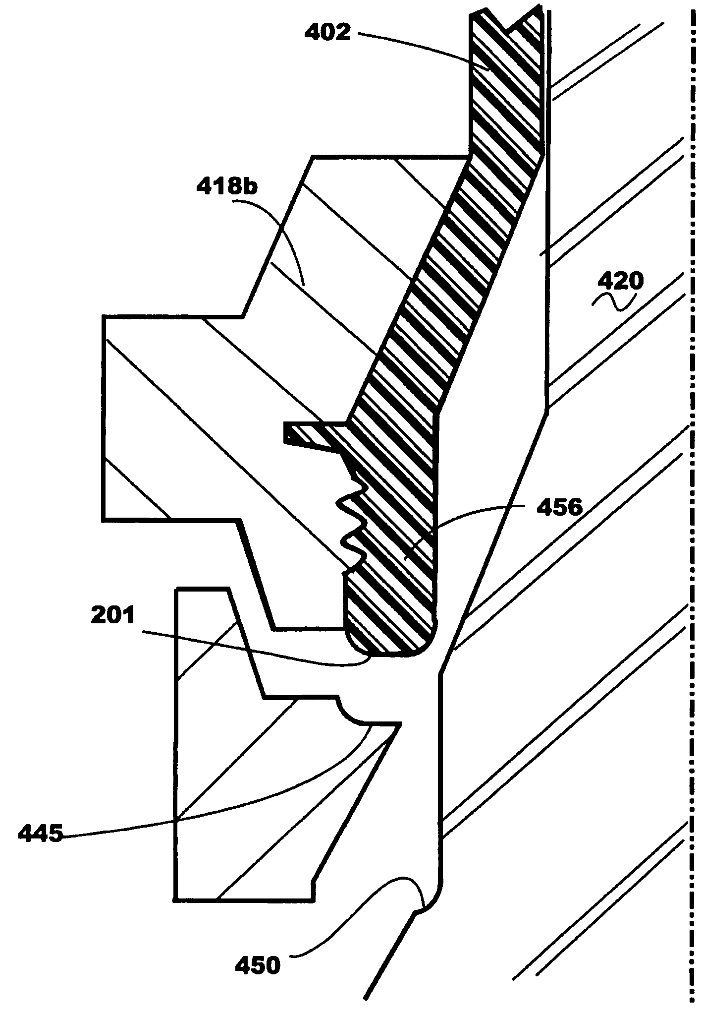
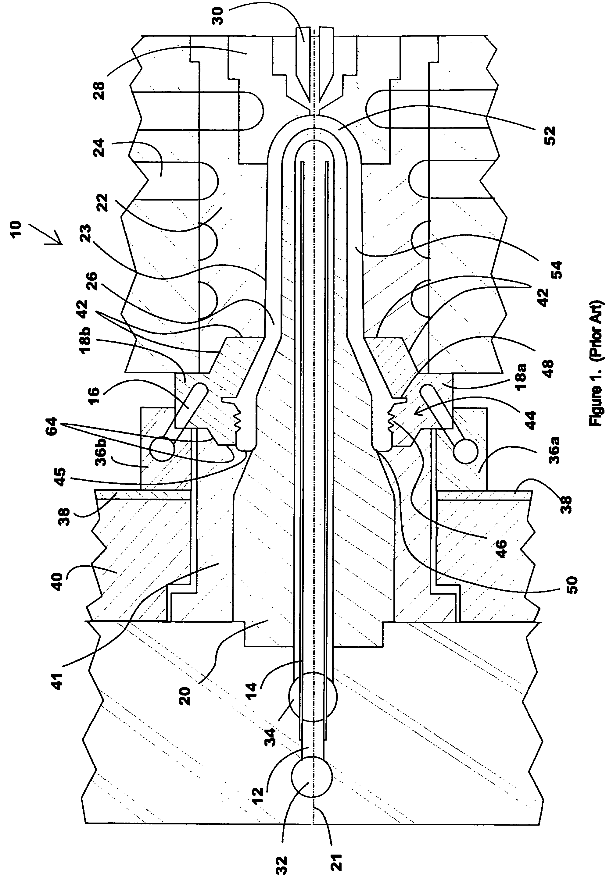
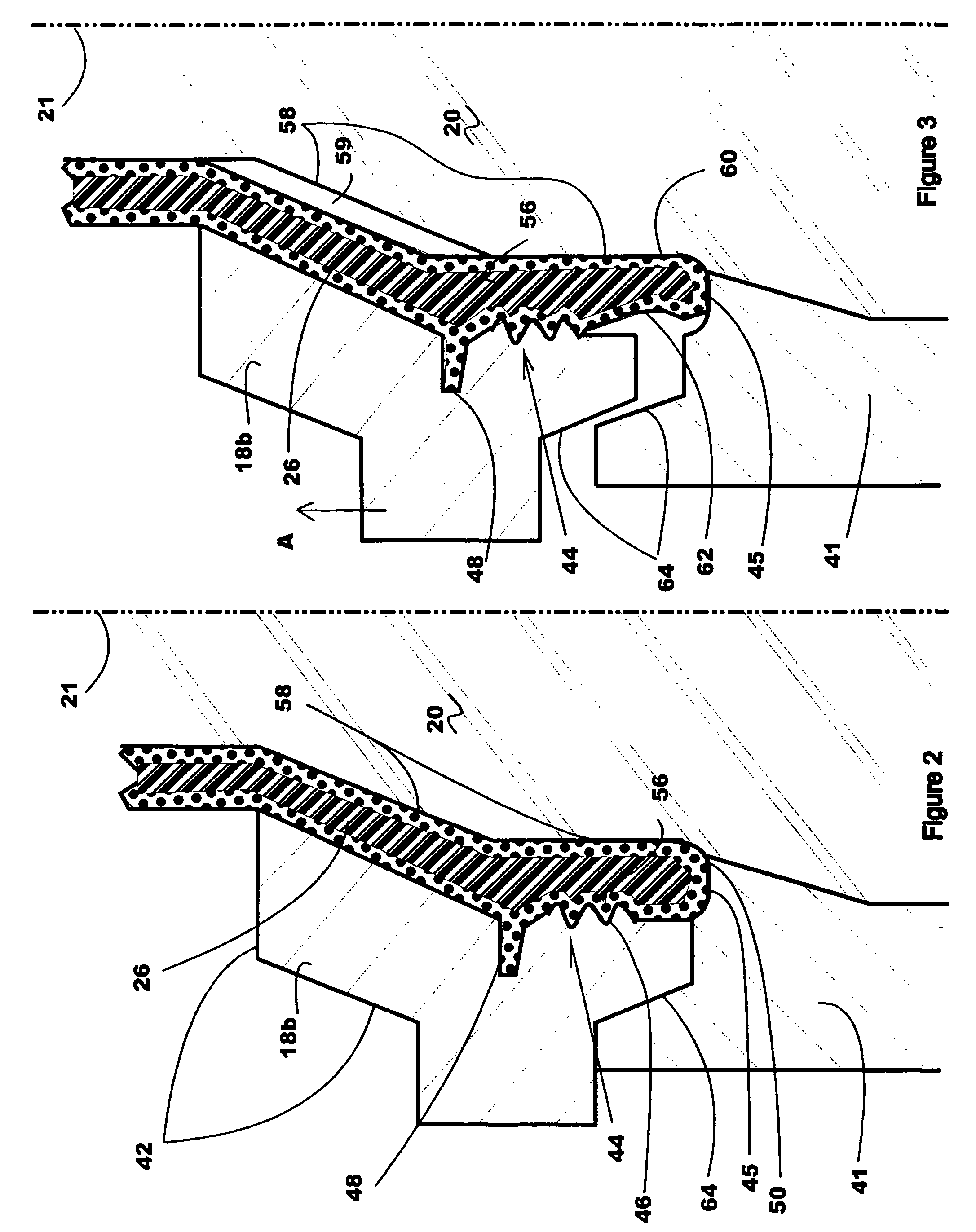
[0044]The present invention will now be described with respect to several embodiments in which a neck ring assembly uses a two stage (or step) stripping action to strip an injection-molded plastic preform from the core, before the preform is completely solidified, thus reducing cycle time. However, the present invention will find applicability in many molding technologies beyond injected-molded plastic preforms, such as the molding of containers, pails, trays, paint cans, tote boxes, and similar products, or other molded products possibly with non-circular cross-sectional shapes, etc.

[0045]In brief, the preferred embodiments of the present invention strip the preform from the core in a first lifting stage by the use of lifting surfaces which act on both the top sealing surface of the preform (the typically circular, open end of the preform where a sealing lid may be affixed, which surface is substantially orthogonal to the longitudinal axis of the preform) and a neck ...


PUM

PropertyMeasurementUnit
timeaaaaaaaaaa
molding timeaaaaaaaaaa
distanceaaaaaaaaaa

Abstract

Injection molding method and apparatus for ejecting a molded plastic preform from a mold. A first lifting structure and / or step is configured to have an inner surface with an area for sealing and aligning with a complementary surface on a core, and to have an upper surface with an area for sealing and aligning with a complementary surface on a second lifting structure, said upper surface of said first lifting structure being configured to lift a molded plastic preform from the injection mold in a lifting direction for a first period of time, the lower portion of the molded plastic preform lying in a plane substantially perpendicular to the lifting direction. A second lifting structure and / or step is configured to have an inner surface configured to lift an outer surface of the molded plastic preform from the injection mold in the lifting direction for a second period of time, the outer surface of the molded plastic preform including structure lying in a plane substantially parallel with the lifting direction.Since the molded plastic preform is lifted by its end, the preform does not have to be solidified at its interior, thus allowing earlier removal of the preform from the mold, reducing cycle time.

Description

BACKGROUND OF THE INVENTION[0001]1. Field of the Invention[0002]The present invention relates to methods and apparatus for injection molding preforms so that their subsequent reheating and blow-molding into containers is simplified. In particular, the present invention relates to a method and apparatus for providing an improved neck-ring or neck split components of an injection mold that allows for an earlier ejection or removal of the preform from the injection mold, thus reducing time needed to manufacture the preform. The method and apparatus are particularly well-suited for thermoplastic polyester polymer materials such as polyethylene terephthalate.[0003]2. Related Art[0004]Well known by those skilled in the art, the preform is a tube with a generally hollow circular cross-sectional configuration having a body portion, a closed end portion with a generally hemispherical configuration, and an open end. About the open end and superimposed between the open end and the body portion...

Claims


Application Information

Patent Timeline
Patent Type & Authority Patents(United States)
IPC IPC(8): B29C45/44B29C45/17B29C45/26B29C45/33B29C45/40
CPCB29C45/40B29K2105/253B29C2045/7264
Inventor MARTIN, SIMON ROY
Owner HUSKY INJECTION MOLDING SYST LTD
Why Eureka
Try Eureka