Tracked vehicle road wheel puller

a technology for pulling wheels and vehicles, applied in vehicle components, metal-working hand tools, metal-working apparatus, etc., can solve the problems of wheel being forcibly disjoined from its associated hub, wheel being removed by force, wheel rust or other chemical erosion, etc., to achieve the effect of quick and efficient removal of road wheels, without inflicting undue damage to wheels, hubs or tracks

Inactive Publication Date: 2009-01-08
PHARAON JEAN W
View PDF11 Cites 1 Cited by
  • Summary
  • Abstract
  • Description
  • Claims
  • Application Information

AI Technical Summary

Benefits of technology

[0016]The present invention discloses a tracked vehicle road wheel puller for forcibly removing, by applying a combined pulling and twisting force, to either or both of outer and inner road wheels associated with a tracked vehicle. In particular, the present invention is an improvement over prior art devices in that it provides a portable and powered device for quickly and efficiently removing a road wheel from an underlying hub and without inflicting undue damage to the wheel, hub or track.

Problems solved by technology

In use, it has been found that removal of road wheels, either through normal wear and tear usage or as a result of some event, can be complicated by force misaliginents occurring between the inner wheel rim and the bolt portion of the axle.
Such resistance to removal can also result from rust or other chemical erosion occurring between either or both of outer and inner wheel components and the underlying axle supported hub.
In one known application, removal of the road wheel is facilitated by the repeated application of a sledgehammer against the outer / inner road wheel components, resulting in the wheel becoming forcibly disjarred from its associated hub.
A drawback of this technique is the undesirable damage caused to both the wheel as well as to the associated vehicle tread, particularly in instances in which the user attempts to remove only the outer wheel component and without the utilization of such as a lifter rod for vertically actuating the entire road wheel assembly.

Method used


Image

  • Tracked vehicle road wheel puller
  • Tracked vehicle road wheel puller
  • Tracked vehicle road wheel puller

Examples


Embodiment Construction

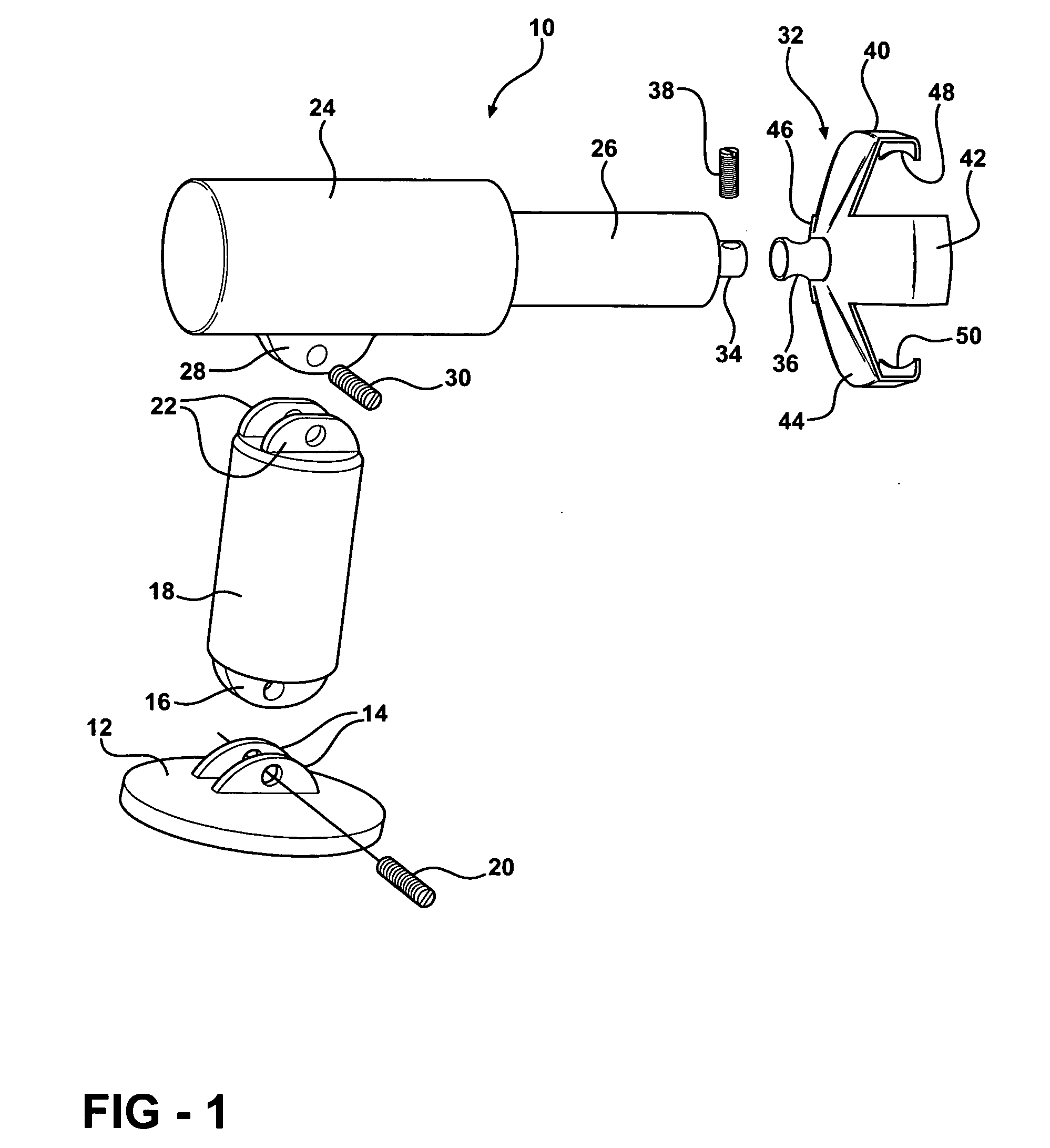
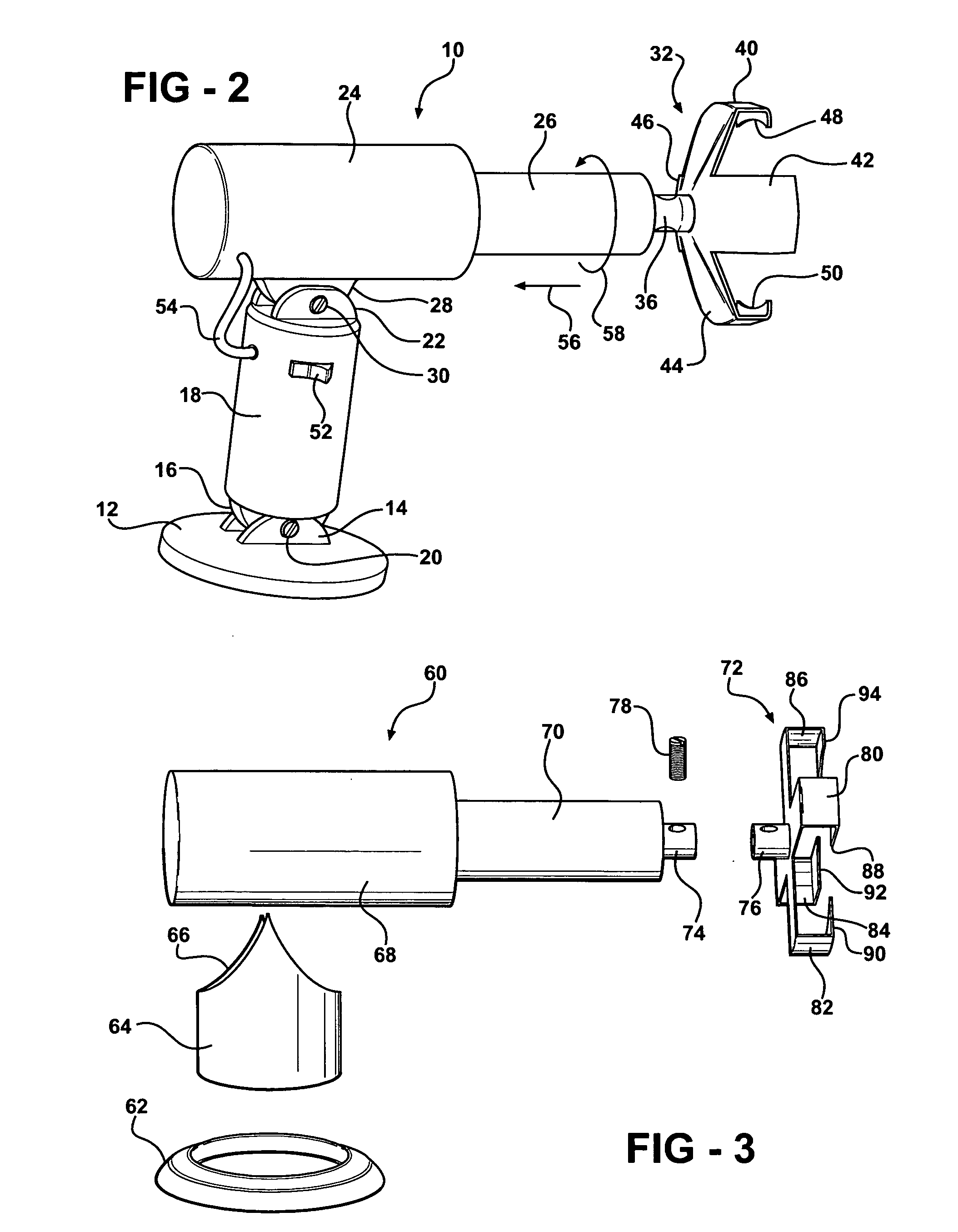
[0026]Referring now to FIG. 1, a powered road wheel puller device is illustrated at 10 according to a first preferred embodiment of the present invention. As previously described, the wheel puller device 10 teaches a ground supported, powered and articulated device exhibiting a clamp fixedly secured to a location of the road wheel and for forcibly removing the wheel from its axle by applying a combined pulling and twisting force.

[0027]As illustrated in FIGS. 1 and 2, the components of the wheel puller assembly 10 include the provision of a base plate 12, such having a substantially flattened and annular overall shape. A pair of spaced apart guide members 14 project from an upper surface of the base plate 12 and locate therebetween a downwardly projecting and seating member 16 associated with a cylinder leg 18. A pin, shown at 20 in FIGS. 1 and 2, seats through the aligning apertures established by the guide members 14 and sandwiched seating member 16.

[0028]A further pair of spaced a...


PUM

PropertyMeasurementUnit
twisting forceaaaaaaaaaa
sizeaaaaaaaaaa
resistanceaaaaaaaaaa

Abstract

A wheel puller assembly for forcibly removing a road wheel from a hub and axle associated with a tracked vehicle. The road wheel further includes outer and inner wheel components bolted to a circular array of lugs extending from the vehicle hub. The assembly includes a substantially flattened and plate-shaped base, a leg extending upwardly from the base and which is typically pivotally connected thereto. A powered cylinder secures to an upper end location of the leg and includes first and second telescoping components terminating in a clamp exhibiting a plurality of radially outwardly extending claws. The claws terminate in inwardly directed fingers for engaging respective locations along an annular rim associated with at least one of the outer and inner road wheel components. The clamp is adapted to engaging a location associated with the road wheel and in order to apply at least one of a pulling and twisting force to forcibly remove the road wheel from the hub.

Description

GOVERNMENT INTEREST[0001]The invention described herein may be manufactured, used, and licensed by or for the United States Government.FIELD OF THE INVENTION[0002]The present invention relates generally to devices for removing a road wheel from such as a tracked vehicle. In particular, the present invention teaches a ground supported, powered and articulated device exhibiting a clamp fixedly secured to a location of the road wheel and for forcibly removing the wheel from its axle by applying a combined pulling and twisting force.BACKGROUND OF THE INVENTION[0003]Tracked vehicles such as tanks are armored personal carriers are known in the art. These include the provision of a plurality of axle-supported road wheels, exhibiting outer rubber surfaces, and which are supported upon a closed loop and outer tread.[0004]Routine maintenance involves replacement of either or both of outer and inner mating components associated with the road wheel, and owing to such as damage to the wheels and...

Claims


Application Information

Patent Timeline
Patent Type & Authority Applications(United States)
IPC IPC(8): B21D53/26
CPCB25B27/026Y10T29/49492B60B29/008
Inventor PHARAON, JEAN W.
Owner PHARAON JEAN W
Why Eureka
Try Eureka