
Buoy split key removal device

a technology of split key and buoy, which is applied in the field of buoy split key, can solve the problems of difficult and dangerous removal process, prior proposed solutions are problematic, and the crew of buoy tenders face severe safety issues, etc., and achieve the effect of quick and efficient buoy split key removal

Active Publication Date: 2014-12-23
US DEPT OF HOMELAND SECURITY
View PDF1 Cites 5 Cited by
  • Summary
  • Abstract
  • Description
  • Claims
  • Application Information

AI Technical Summary

Benefits of technology

The patent aims to improve the process of removing buoy split keys by making it safer, efficient, and faster. The technical effects of the patent are its ability to provide quick and effective buoy split key removal.

Problems solved by technology

Buoy tender crews face severe safety issues when removing split keys from a buoy shackle.
When in the water, the split key often becomes mangled, resulting in a difficult and dangerous removal process.
Prior proposed solutions are problematic as grave safety issues arise during buoy split key removal using brute force and a hammer alone.
Numerous people are often injured using the current method which consisted of using a pair of 8 lbs hammers.
In the second scenario, the split key is foul, bent, and / or twisted to odd angles of distortion which make it difficult to remove using the hammer method described in the first scenario.
When the split key is bent between 90 to 140 degrees with a slight twist, removal of the split key problematically requires working with a chisel or a wedge prior to removal with a sledge hammer.
There is no easy or safe way to get the split key off with any kind of hand held tools.
The second and third scenarios describe time consuming, inefficient, and unworkable proposed solutions to removing a bent split key.

Method used


Image

  • Buoy split key removal device
  • Buoy split key removal device
  • Buoy split key removal device

Examples


second alternate embodiment

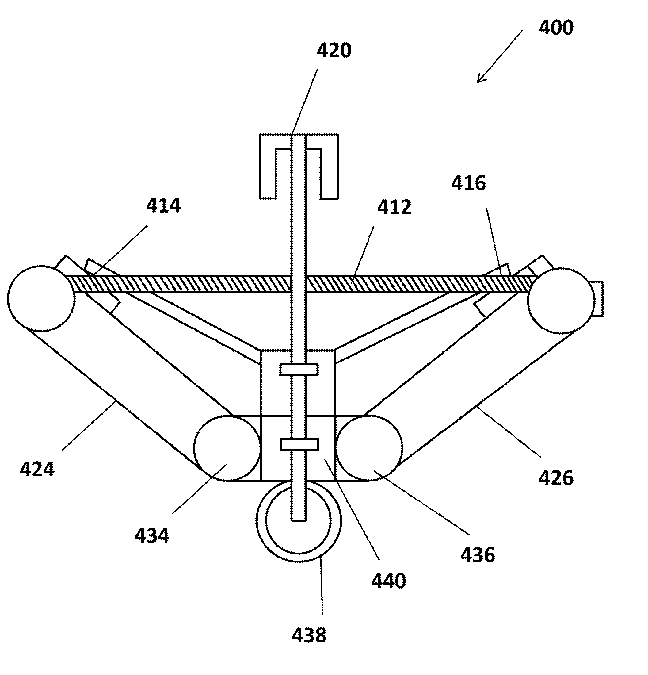
[0064]FIG. 5 illustrates a pictorial illustration 500 of a second alternate embodiment of the disclosed BSD. A prototype of the device was crafted from using half of a car jack and A36 steel plates. This prototype was tested for closing of a 4th class split key and a 1st class split key that were spread to a 140°. The prototype was also tested with manual closing as well as using an external power source such as a cordless power drill. The prototype successfully closes the split key in less than 45 sec.

[0065]Second Alternate Embodiment Laboratory Testing

[0066]The Buoy Split Key Removal Device second alternate embodiment was placed on top of a table. The buoy split key was placed into the pin and butterflied out to 140° from the centerline. The shackle pin was then set into the angle steel on the base of the prototype. Spacer plates were inserted in between the split key and the compression plates to ensure that the split key would be fully compressed when the prototype was in the cl...

third alternate embodiment

[0070]FIG. 6 illustrates a pictorial illustration 600 of a third alternate embodiment of the disclosed BSD. The tail clamp of the Buoy Split Key Removal Device second alternate embodiment was redesigned and the device mounted on a block similar to what is used in the heat and beat process. This would provide for a more stable platform to work with. The BSD second alternate embodiment was mounted to make it more user friendly and fleet applicable. This design change will change several of the design parameters previously established. The device will no longer weigh less than twenty pounds. The device will still be operable by a single person. The redesigned configuration will contain a more complicated mechanism but will require fewer steps to complete the process to extract the split key from the shackle.

[0071]Mounting the device allowed redesign of the tail clamp to make that process faster and easier for the user. The block would provide a place to rest the chain while it is being...


PUM

PropertyMeasurementUnit
bending stressaaaaaaaaaa
diameteraaaaaaaaaa
thread angleaaaaaaaaaa

Abstract

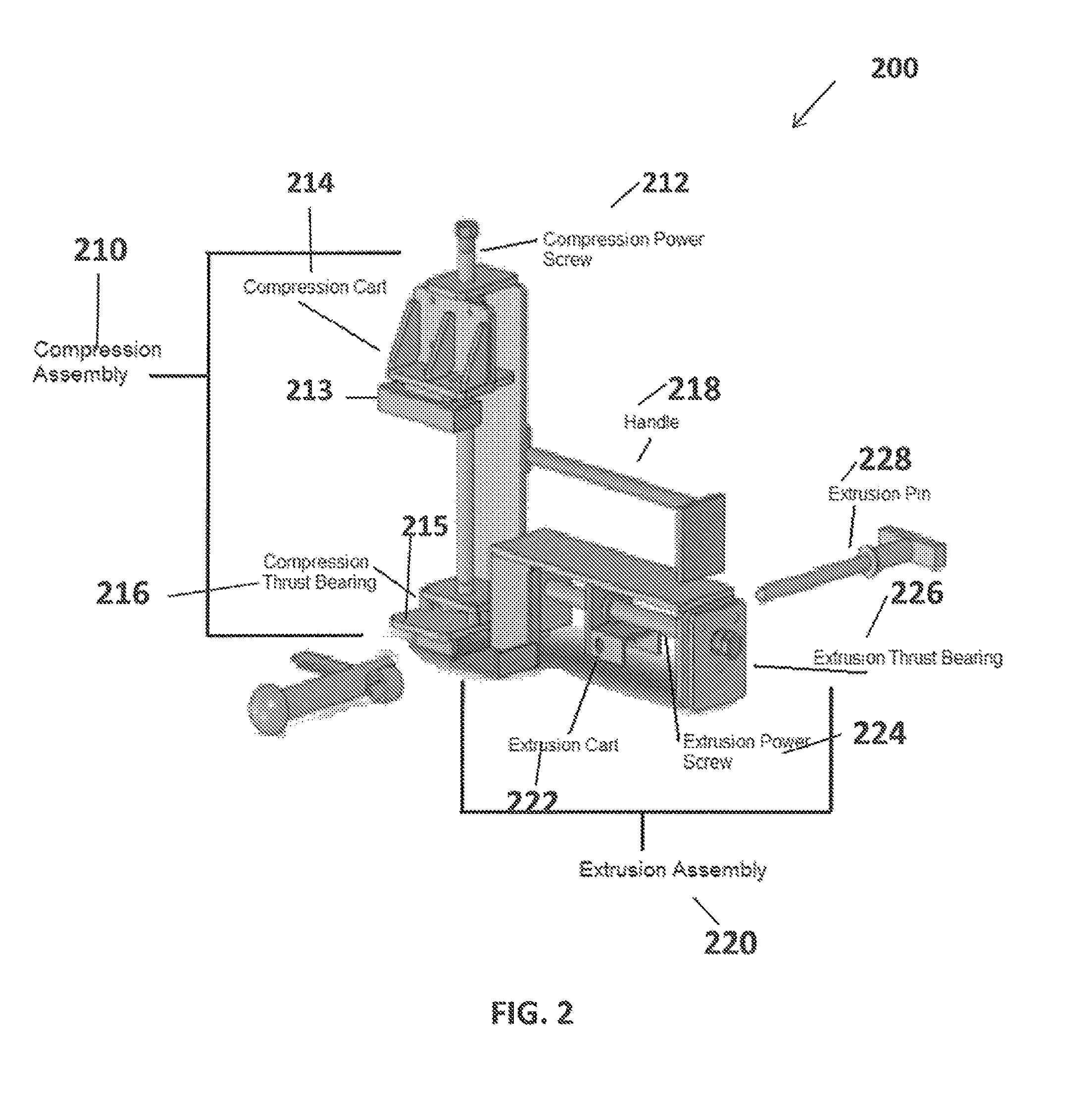
A buoy split key (“BSD”) removal apparatus, system, and method are disclosed. The BSD utilizes a power screw to apply a steady and controllable compressive load onto the split key. The BSD applies a compressive force or load to the bitter ends of the split key in order to maximize the use of the moment on the split key. The spread and / or twisted split key is compressed by a compression assembly and compression power screw as supported by a compression frame. The compression assembly provides steady and controllable compression on a buoy split key. A compression power screw and extrusion power screw should be threaded in the opposite direction for maximum torque to remove the buoy split key. Once the split key is fully compressed by the compression assembly, the compressive load from the power screw and split key are then removed.

Description

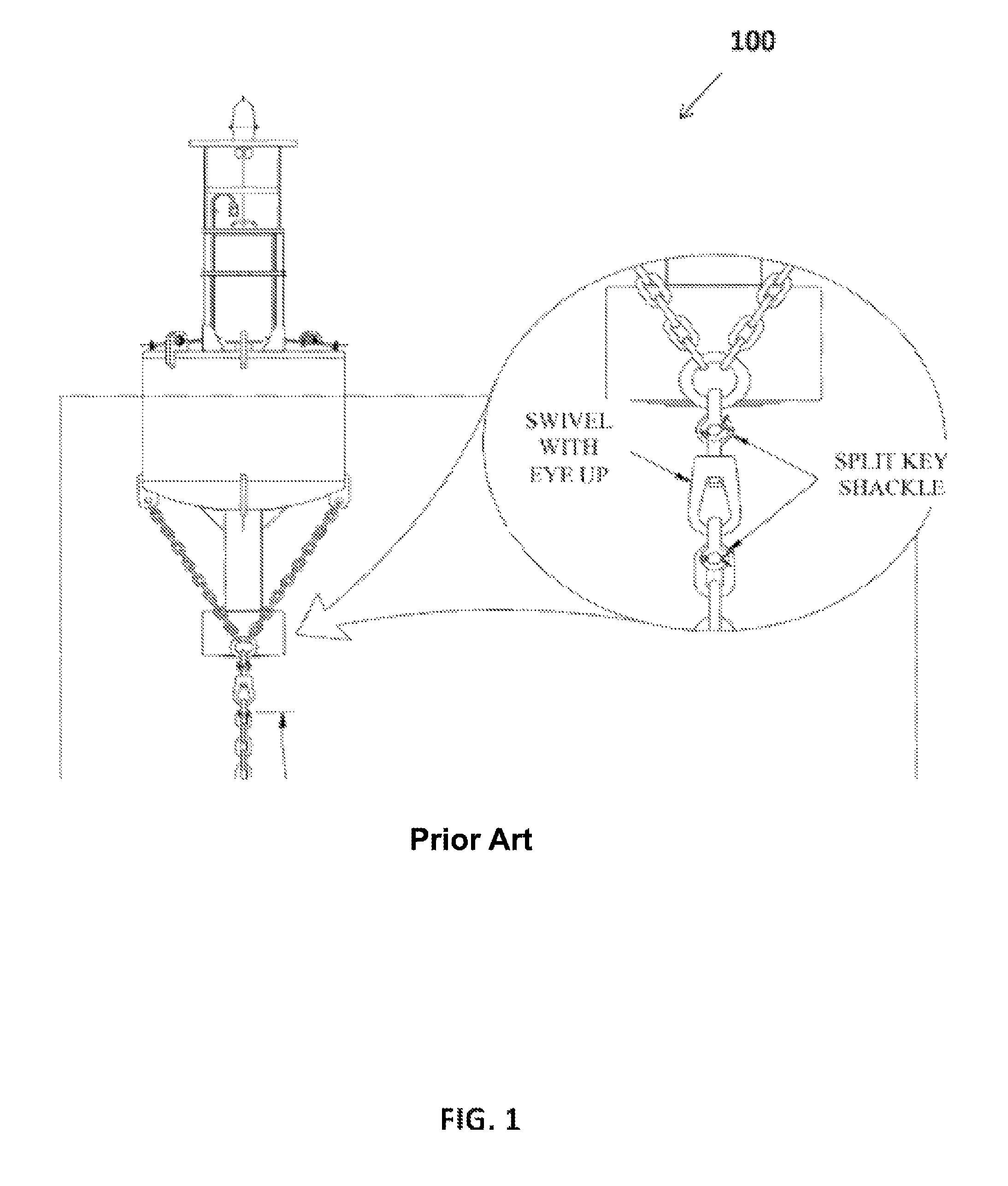
STATEMENT REGARDING FEDERALLY SPONSORED RESEARCH OR DEVELOPMENT[0001]The United States of America may have certain rights to this invention under the Secretary of the Department of Homeland Security and the Commandant of the United States Coast Guard. All embodiments herein were invented by cadets and their advisors at the United States Coast Guard Academy.TECHNICAL FIELD[0002]The disclosed embodiments relate to buoy split keys. The disclosed embodiments further relate to devices for safely and efficiently removing buoy split keys. The disclosed embodiments also relate to compressing buoy split keys when bent and twisted.BACKGROUND OF THE INVENTION[0003]Buoy tender crews face severe safety issues when removing split keys from a buoy shackle. A buoy is weighed down to the floor of the body of water by a chain attached to a concrete block. The chain connects the buoy by a shackle, held shut by a pin and split key, as shown in the exemplary pictorial illustration 100 of FIG. 1. The spl...

Claims


Application Information

Patent Timeline
Patent Type & Authority Patents(United States)
IPC IPC(8): B23P19/00B63B22/08B63B22/04
CPCB63B22/04B63B21/04Y10T29/49824
Inventor ROZZI-OCHS, JESSICAJACOBSON, BRETNAGY, KHIEMNOLAN, ERINRICE, EVANTROCH, SARAH
Owner US DEPT OF HOMELAND SECURITY
Learn More