
Laundry treatment apparatus and method of controlling the same

a technology of laundry treatment and treatment apparatus, which is applied in the direction of washing machines with receptacles, other washing machines, textiles and paper, etc., can solve the problems of drying machines having such a heat pump with a complicated structure, poor efficiency of air-heating methods, and deterioration of the performance of electric heaters, so as to improve heating efficiency and reduce the risk of deterioration. , the effect of increasing the density of the coil

Active Publication Date: 2019-02-14
LG ELECTRONICS INC
View PDF3 Cites 15 Cited by
  • Summary
  • Abstract
  • Description
  • Claims
  • Application Information

AI Technical Summary

Benefits of technology

The present invention is about a laundry treatment apparatus that uses induction heating to improve efficiency and safety. The aim is to enhance heating efficiency by reducing the interval between the coil of the induction module and the drum and to mount the induction module more stably on the outer surface of the tub. This will lead to better performance of the apparatus and improved user experience.

Problems solved by technology

Thus, foreign substances such as scale may accumulate on the electric heater, which may lead to deterioration in the performance of the electric heater.
However, such an air-heating method has generally poor efficiency.
However, a drying machine having such a heat pump has a complicated structure, and the manufacturing costs thereof are high.
However, these related art documents disclose only a basic concept of induction heating for a washing machine, and do not disclose concrete constituent components of an induction heating module, connection and operational relationships with the constituent components of a laundry treatment apparatus, or a concrete method or configuration for improving efficiency and securing safety.

Method used


Image

  • Laundry treatment apparatus and method of controlling the same
  • Laundry treatment apparatus and method of controlling the same
  • Laundry treatment apparatus and method of controlling the same

Examples


Embodiment Construction

[0073]Reference will now be made in detail to the preferred embodiments of the present invention, examples of which are illustrated in the accompanying drawings. Meanwhile, elements or control methods of apparatuses which will be described below are only intended to describe the embodiments of the present invention and are not intended to restrict the scope of the present invention. Wherever possible, the same reference numbers will be used throughout the drawings to refer to the same or like parts.

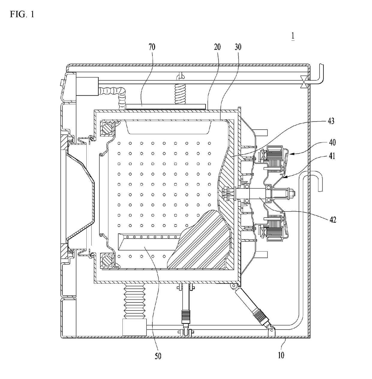
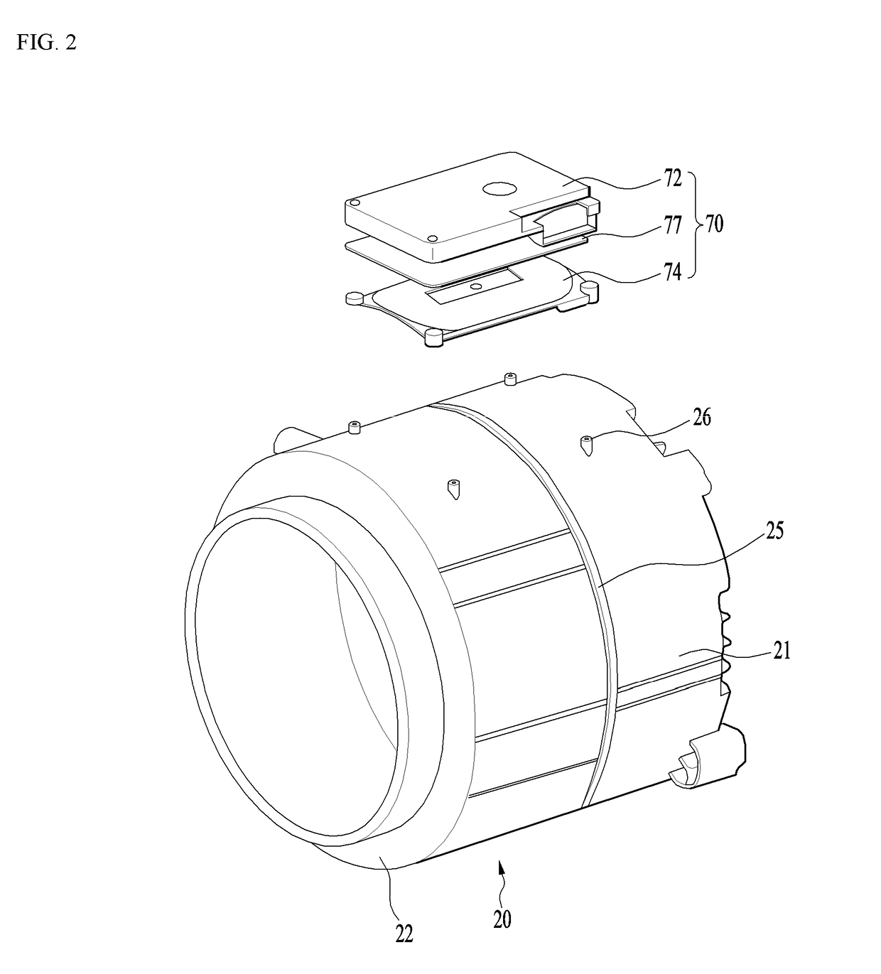
[0074]As shown in FIG. 1, a laundry treatment apparatus according to an embodiment of the present invention may include a cabinet 10 forming the external appearance of the laundry treatment apparatus, a tub 20, a drum 30, and an induction module 70 for heating the drum 30.

[0075]The tub 20 may be provided in the cabinet 10 to accommodate the drum therein. The tub may be provided in the front side thereof with an opening. The drum 30 is rotatably provided in the tub to contain laundry there...


PUM


Abstract

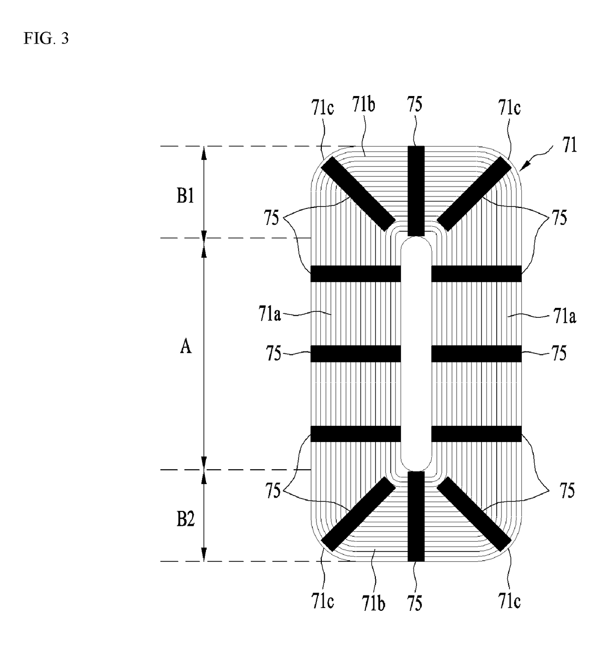
A laundry treatment apparatus is configured to directly heat a drum containing laundry therein. The laundry treatment apparatus includes: a tub; a drum configured to rotate within the tub and to contain laundry therein, the drum being formed of a metallic material; and an induction module provided at an outer surface of the tub and configured to heat a surface of the drum within the tub via induction, the induction module comprising: a coil that comprises a wire through which an electric current is configured to pass so as to generate a magnetic field; a base housing configured to accommodate the coil therein, the base housing being mounted on the outer surface of the tub; an at least one magnet configured to be arranged above the base housing in which the coil is accommodated, and arranged to be lengthwise perpendicular to a longitudinal direction of the wire of the coil.

Description

[0001]This application claims the benefit of Korean Patent Application No. 10-2017-0101334, filed on Aug. 9, 2017, which is hereby incorporated by reference as if fully set forth herein.BACKGROUND OF THE INVENTIONField of the Invention[0002]The present invention relates to a laundry treatment apparatus, and more particularly, to a laundry treatment apparatus configured to directly heat a drum containing laundry therein.Discussion of the Related Art[0003]Generally, laundry treatment apparatuses are apparatuses for treating laundry, specifically, for washing, drying or refreshing laundry.[0004]There are various kinds of laundry treatment apparatuses, for example, a washing machine mainly adapted to wash laundry, a drying machine mainly adapted to dry laundry, and a refresher mainly adapted to refresh laundry.[0005]There is also a laundry treatment apparatus that can perform at least two laundry-treating processes, among washing, drying and refreshing, in a single body. For example, a ...

Claims


Application Information

Patent Timeline
IPC IPC(8): D06F39/04D06F23/04D06F37/12D06F37/26H05B6/10
CPCD06F39/04D06F23/04D06F37/12D06F37/267H05B6/102H05B6/108D06F58/26D06F34/24D06F2103/52D06F2105/28
Inventor KIM, BEOMJUNPARK, BIOHONG, SANGWOOK
Owner LG ELECTRONICS INC
Learn More