Method for processing infectious waste and system for the same

a technology of infectious waste and processing method, applied in grain treatment, drying machines, light and heating equipment, etc., can solve the problems of large amount of fresh liquid that requires a long period of time, large equipment, environmental problems, etc., and achieve the effect of increasing the efficiency and safety of treating

Active Publication Date: 2006-04-25
STERASSURE SOLUTIONS
View PDF23 Cites 13 Cited by
  • Summary
  • Abstract
  • Description
  • Claims
  • Application Information

AI Technical Summary

Benefits of technology

[0006]The present subject matter recognizes and addresses the above briefly discussed drawbacks, and others of above-described processes and systems for treating infectious waste. Accordingly, a general aspect of the present subject matter is to provide a process and a system, as well as different components of the system, that can increase the efficiency and safety of treating infectious waste. Additional aspects and advantages of the invention will be set forth in part in the following description, or may be obvious from the description, or may be learned through practice of the invention.
[0010]A holding tank is connected to the processing chamber. The holding tank supplies the processing water at the elevated temperature sufficient to process the infectious waste in the processing chamber. A filter is disposed between the processing chamber and the holding tank. The filter cleans the processing water that exits the processing chamber and supplies at least a portion of the filtered processing water back to the holding tank to be reused in the processing chamber. In this manner, water can be recycled increasing the efficiency of the processing system.
[0012]An agitator extends within the processing chamber. The agitator has a rotatable internal shaft possessing an axis extending through the process chamber with a tapered blade carrier disposed on a free end of the shaft. A plurality of blades are pivoted about pivot points on the tapered blade carrier. The blades are spring-loaded and are biased upward parallel to the axis of the internal shaft at rest. Upon rotation of the shaft, centrifugal force causes the blades to extend outward from the blade carrier about the pivot points into an angular position as measured from the axis of the internal shaft. The agitator spins the blades within the processing chamber when the processing chamber is filled with heated water and infectious waste, thereby mixing the heated water and infectious waste thoroughly to biologically neutralize the infectious waste by rapidly exposing the waste to the heat in the water.
[0015]A plurality of blades is pivotally connectable to the tapered blade carrier with the blades being spaced about the free end of the blade carrier. Springs are carried by the blade carrier and in communication with the blades and the blade carrier. The springs bias the blades upward about parallel to the axis of the internal shaft when the blades are in a resting position. The blades are then extendable upon rotation of the shaft to outward positions from the blade carrier about the pivot points as measured from the axis of the internal shaft due to centrifugal force. In this manner, the blades can interact with the processing water and waste without becoming immobilized by the waste.

Problems solved by technology

These processes often require large expensive equipment and can pose environmental problems.
These systems required large quantities of fresh liquid that require a long period of time to heat to the desired processing temperature.
Such use of large quantities of liquid is costly not only in the use of the large quantity of liquid, but also through the large expenditure of energy needed to heat each batch of the liquid to the desired temperature.
The pumps are prone to clogging by flexible waste such as tubing and textile waste that wraps around the blades and are subject to damage by metal objects such as clamps, scalpel blade holders.
Due to the construction of the system, these pumps are hard to access and clean.
Further, when the pump inevitably fails, repair is difficult and dangerous because the pump and system are clogged with infectious waste.
Further, due to the massive size of these systems it is nearly impossible to remove the system for off-site repair.

Method used


Image

  • Method for processing infectious waste and system for the same
  • Method for processing infectious waste and system for the same
  • Method for processing infectious waste and system for the same

Examples


Embodiment Construction

[0034]Reference will now be made in detail to the presently preferred embodiments of the invention, one or more examples of which are shown in the figures. Each example is provided to explain the invention, and not as a limitation of the invention. In fact, features illustrated or described as part of one embodiment can be used with another embodiment to yield still a further embodiment. It is intended that the present invention cover such modifications and variations.

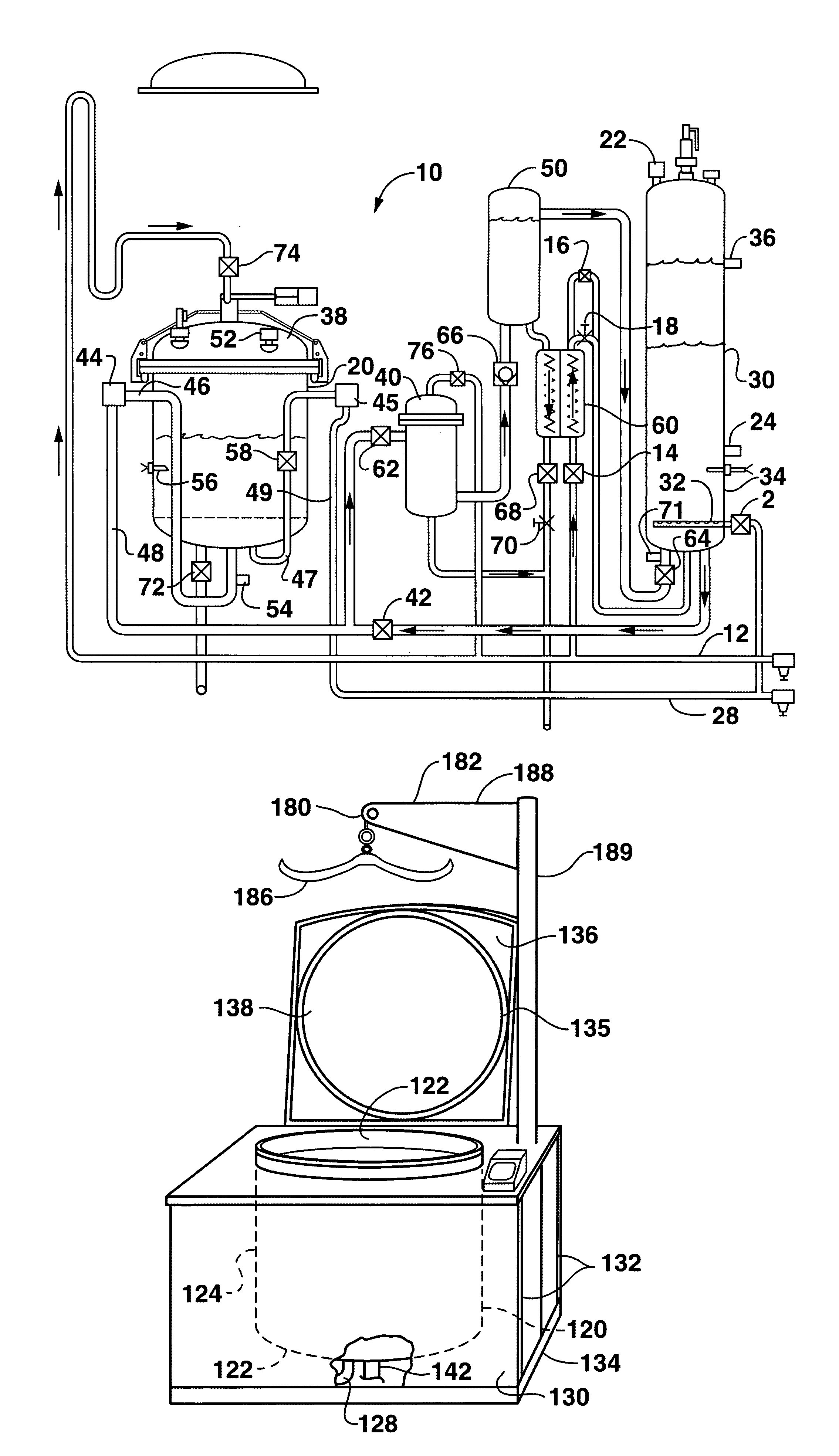
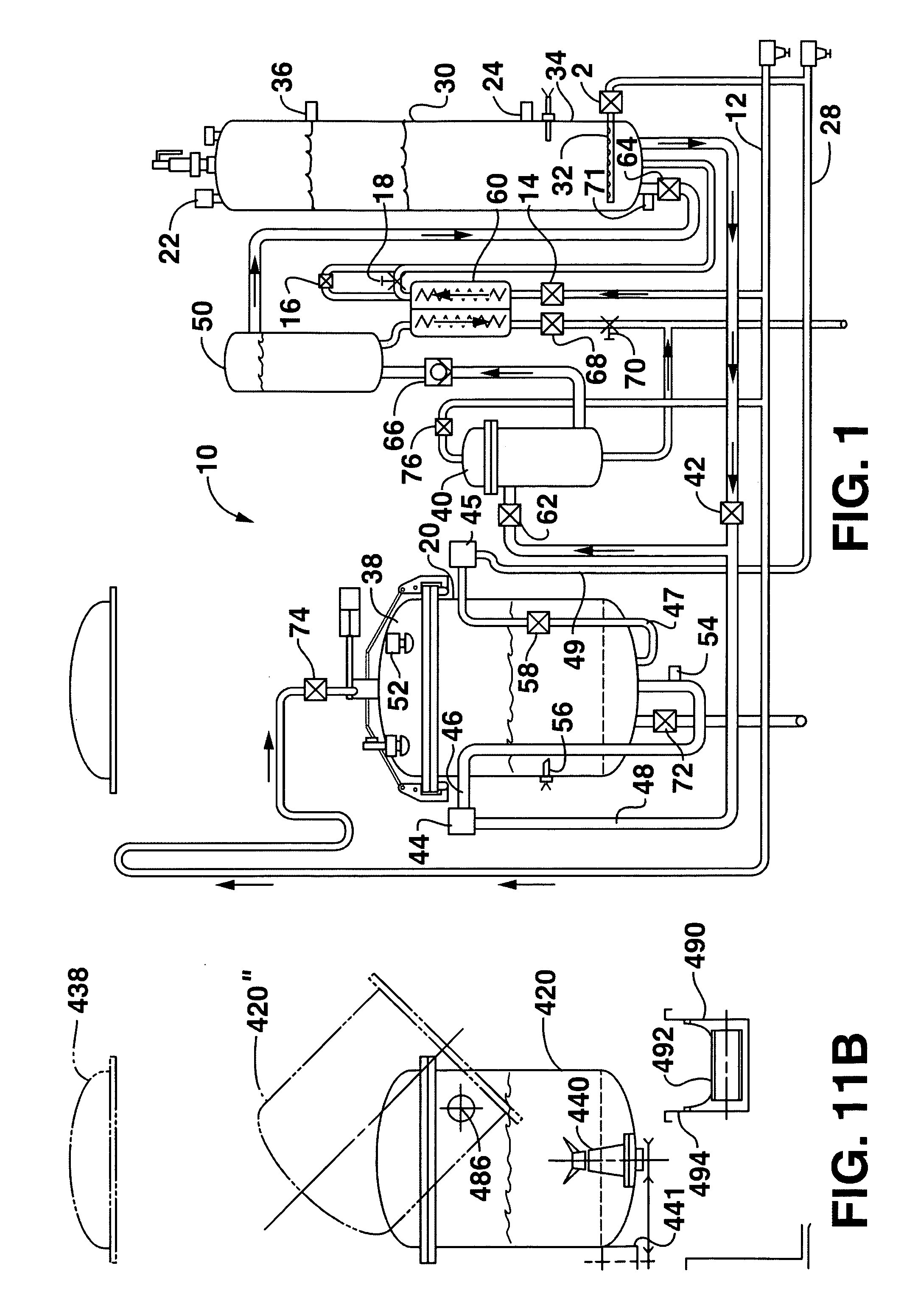
[0035]FIG. 1 illustrates a system, generally 10, for processing infectious waste to biologically neutralize the waste so that the waste may be safely discarded or recycled. The system 10 includes a processing chamber 20, a holding tank 30, a filter 40, a transfer tank 50 and a heat exchanger 60 that are used to neutralize infectious waste using superheated water, while recycling at least a portion of the water to be reused again in the process. Thereby, efficiency of the processing of infectious waste can be increased ...


PUM


Abstract

A processor and method for treating infectious waste utilizes a processing chamber having an inlet for delivering processing water at an elevated temperature and under pressure into the processing chamber, an opening in the processing chamber for receiving of infectious waste and for removing treated waste, an agitator for opening the waste material to the action of the water at elevated temperature and pressure. A basket and / or a sieve may be carried in the processing chamber to facilitate drainage of spent processing water, and an apparatus may be included for removing neutralized waste through the opening in the processing chamber either by inverting the processor or by removing and inverting the basket and / or sieve.

Description

TECHNICAL FIELD OF THE INVENTION[0001]This invention relates to a method useful for treating infectious waste as well as a system and processing apparatuses for carrying out the method.BACKGROUND OF THE INVENTION[0002]Currently, medical and biological waste, generally referred to herein as “infectious waste,” generated in hospitals and other medical and research related facilities that contain disease-producing organisms or pathological wastes may be disposed through several disposal processes such as steam sterilization, microwave or plasma radiation, or incineration. These processes often require large expensive equipment and can pose environmental problems.[0003]Systems for using hot liquids to sterilize the infectious waste have also been developed. These systems employ large tanks wherein a pump for chopping and circulating the waste material through the system circuit is contained within the system. These systems required large quantities of fresh liquid that require a long pe...

Claims


Application Information

Patent Timeline
Patent Type & Authority Patents(United States)
IPC IPC(8): F26B21/06
CPCA61L11/00F16J13/06B09B3/0075
Inventor SMITH, DONALD L.
Owner STERASSURE SOLUTIONS
Why Eureka
Try Eureka