Adjustable height inlet/outlet liquid level management tools and systems

a technology of liquid level management and adjustable height, which is applied in the direction of liquid transferring devices, machines/engines, packaging, etc., can solve the problems of time-consuming and expensive process, expensive to dispose of properly, and unnecessary vehicular traffic, so as to reduce traffic, efficiently and quickly read and record, and eliminate the coordination of the arrival of water trucks and oil trucks

Inactive Publication Date: 2010-04-27
GIRAFFE LIQUID MANAGEMENT SYST
View PDF13 Cites 13 Cited by
  • Summary
  • Abstract
  • Description
  • Claims
  • Application Information

AI Technical Summary

Benefits of technology

[0029]Thus, it is an object of the present invention to manage the liquids at gas wells compressor stations and water plants and at other containers of stratified liquids to reduce vehicular traffic and to improve the efficiency and safety of operation. By managing the liquids, fuller loads may be transferred to reduce vehicular traffic.
[0070]A variable height outlet tool is also used in each oil sale storage tank to assure that the oil removed through the orifice of the tool is devoid of any BS&W in the bottom of the tank. If the oil is contaminated and loaded into an oil truck anyway, the oil will be rejected at the refinery and the time in loading and transporting the contaminated light oil will result in wasted truck and personnel time. The refinery is often 50 miles or more away from the water plant, and it is important that the transported oil is clean. Consequently, the use of a variable height outlet positioned sufficiently above the BS&W in the bottom of the tank avoids expensive contamination of the light oil.

Problems solved by technology

This is a time consuming and expensive process and involves unnecessary vehicular traffic.
The liquids in this zone have little value (depending on recoverable hydrocarbons), and are expensive to dispose of properly.
It has no value but still must be disposed of, which is expensive.
To perform these operations on each storage tank when there is one or more storage tanks at a well site, compressor station or water plant, requires coordination of arrival of water trucks and oil trucks and, more importantly, involves considerable vehicular traffic.
The vehicular traffic can be very disruptive and can significantly impact serenity and beauty of a pristine area.

Method used


Image

  • Adjustable height inlet/outlet liquid level management tools and systems
  • Adjustable height inlet/outlet liquid level management tools and systems
  • Adjustable height inlet/outlet liquid level management tools and systems

Examples


Embodiment Construction

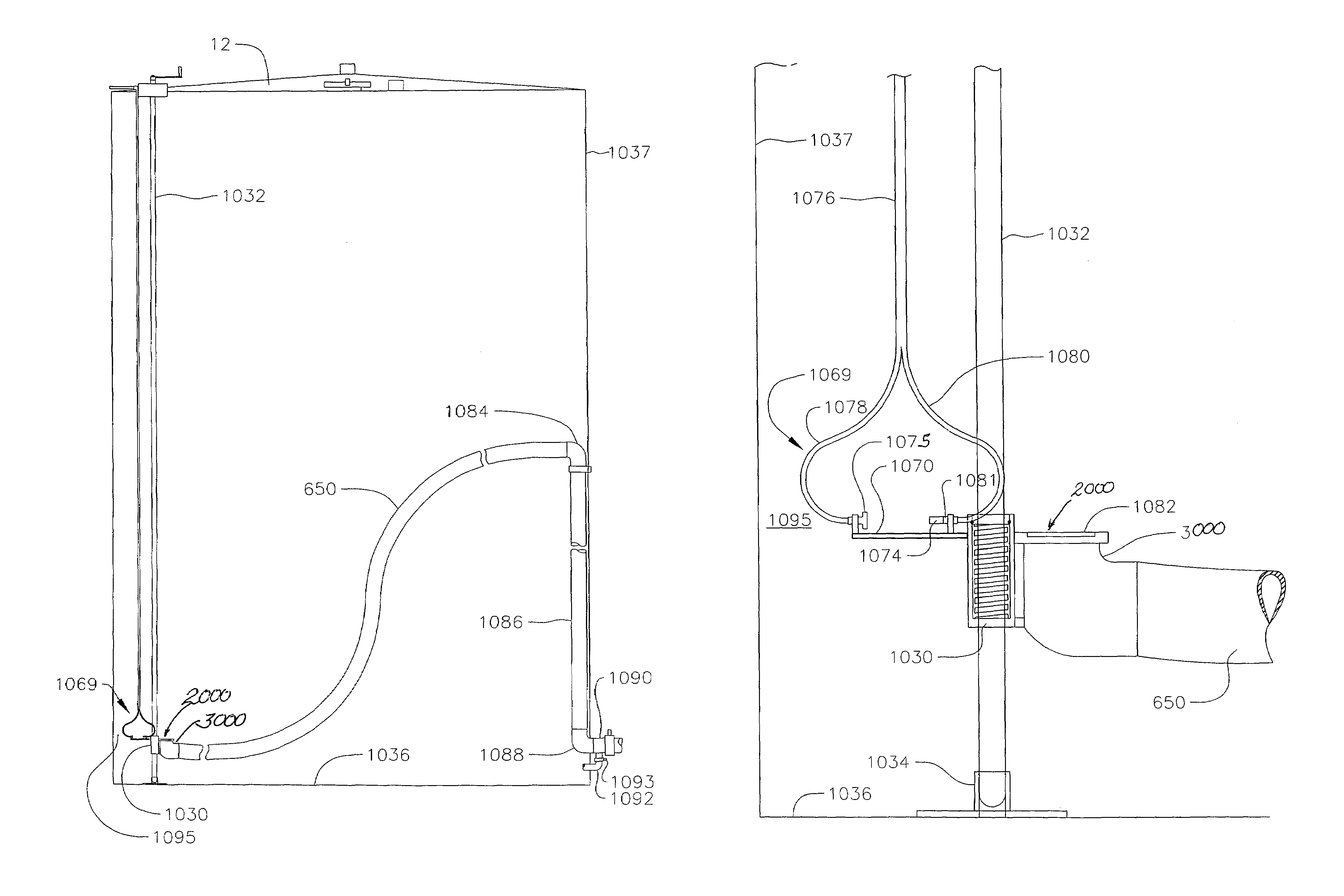
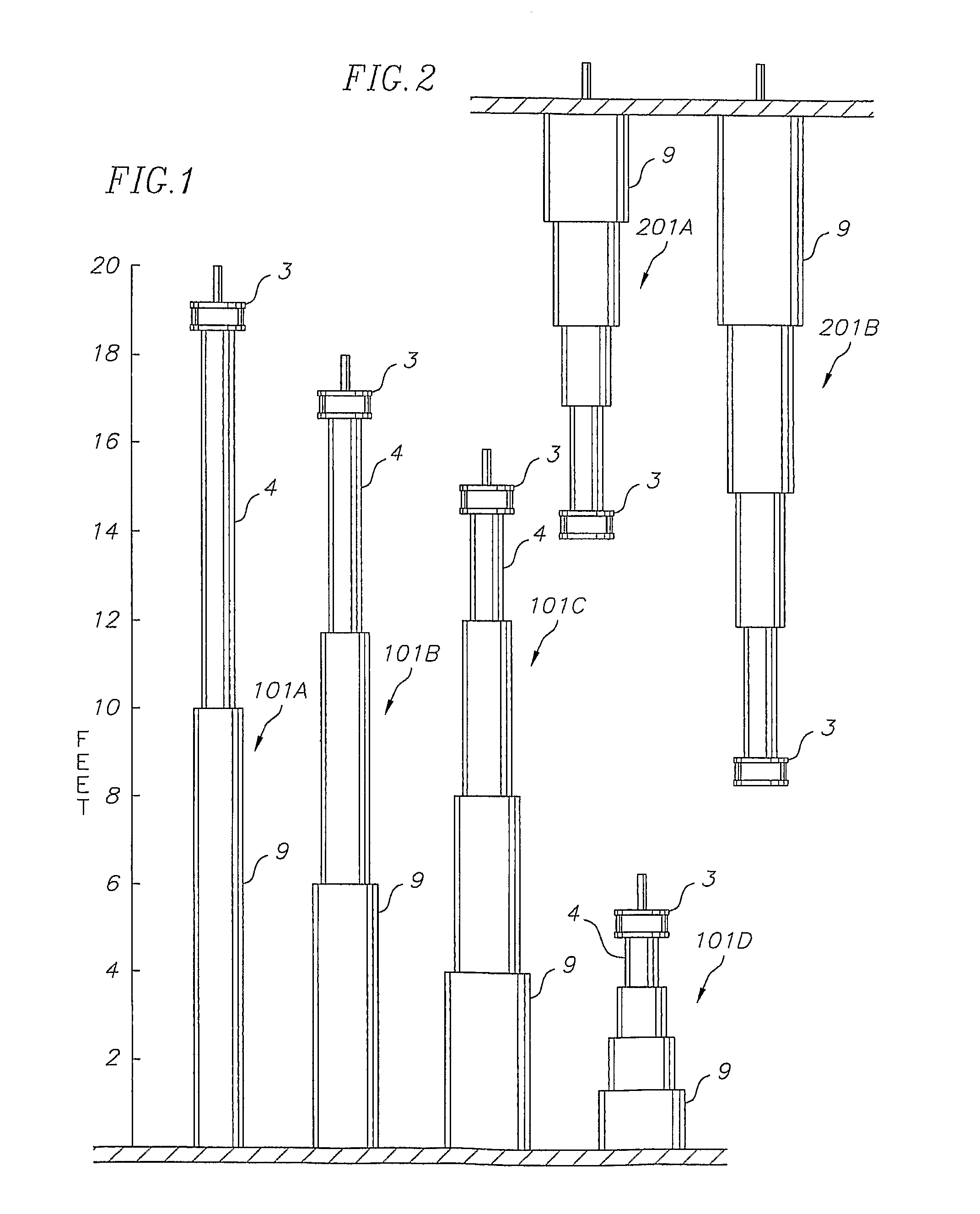
[0172]The design and operation of the liquid management tools of this invention are schematically shown in FIGS. 1-4. The tool in each case is shown in a container 12 having a height of 20 feet. This height is not limiting as to the use of the tool. It is, however, representative of the normal height of 400-barrel and 500-barrel storage tanks used in gas fields.

[0173]Essentially, all levels of a container may be accessed by using one or more of the various tools illustrated in FIGS. 1-4. For example, the upper half of a container, whether it be 20 feet high or some other height, may be accessed by a single-stage tool 101A. This tool has a standpipe section 9, that is generally attached to or supported by the container, and a telescoping tube 4 that telescopes up from the top of the standpipe section 9. The telescoping tube carries an inlet / outlet assembly 3 which may be selectively positioned in the upper half of the container to access selected liquids that are stratified in the up...


PUM

PropertyMeasurementUnit
heightaaaaaaaaaa
heightaaaaaaaaaa
heightaaaaaaaaaa

Abstract

Apparatus for managing layers of different density includes an enclosed tank for holding the liquids so that they stratify into separate layers of different levels in the tank. A conduit for liquid in the tank is open at an inner end to the tank interior, and is open at an outer end to the tank exterior. A drive moves the inner end of the conduit to different levels within tank so liquid can be transferred into or out of different levels in the tank.

Description

CROSS-REFERENCE TO RELATED APPLICATIONS[0001]This application claims priority to provisional application U.S. Ser. No. 60 / 713,627 filed Sep. 2, 2005, to provisional application U.S. Ser. No. 60 / 707,698 filed Aug. 12, 2005, to provisional application U.S. Ser. No. 60 / 688,462 filed Jun. 8, 2005, and to provisional application U.S. Ser. No. 60 / 651,239 filed Feb. 9, 2005.FIELD OF THE INVENTION[0002]This invention relates to the management of stratified liquids in a container, and more particularly, to the management of stratified liquids in potentially explosive environment and / or corrosive and / or poisonous environments by use of variable height inlet / outlet liquid management tools, to the maintenance of the tools and to the automation of the management of stratified liquids.BACKGROUND OF THE INVENTION[0003]Mixed liquids having differing specific gravities will naturally stratify while standing in a container. This occurs with many liquids in many different disciplines. For example, liq...

Claims


Application Information

Patent Timeline
Patent Type & Authority Patents(United States)
IPC IPC(8): B01D17/032B67D7/06
CPCB01D17/0214B67D7/061Y10T74/19851Y10T137/86236Y10T137/86348Y10T137/86372
Inventor HASLEM, KEITH R.
Owner GIRAFFE LIQUID MANAGEMENT SYST
Why Eureka
Try Eureka