Paper Money Processing Apparatus Having Structure for Easily Preventing Paper Money Jams

a processing apparatus and paper money technology, applied in the direction of thin material processing, instruments, article separation, etc., can solve the problems of jamming paper money, difficult to remove paper money jamming, access or approach to the transfer path section, and narrow height of drop door, so as to remove jamming paper money quickly and efficiently, and use space efficiently

Active Publication Date: 2013-05-09
KISAN ELECTRONICS
View PDF8 Cites 5 Cited by
  • Summary
  • Abstract
  • Description
  • Claims
  • Application Information

AI Technical Summary

Benefits of technology

[0013]When a paper money jam occurs the whole transfer path is opened. Therefore, a user can find a position of the jam easily and remove the jammed paper money quickly and efficiently.
[0014]Further, the user can open the whole transfer path by one time opening operation in case of opening the transfer path to remove the jam. Therefore, the user feels convenient and can use the space efficiently because both the front outer part 33 and the back-side outer part 32 of the conventional paper money processing apparatus 30 are opened forward toward the user.
[0015]Additionally, in case of jamming in a back-side transfer path section A (40a), the paper money processing apparatus in the prior art requires the wide space enough to pull the back outer part 33 backward to open the back-side transfer path section A (40a). Thus, there has been inconvenience to the user in that the paper money processing apparatus has to be installed with enough space or gap apart from the wall (or partition) or to be moved forward to be apart enough from the wall. The present invention provides convenience and efficiency when using the apparatus.

Problems solved by technology

In case of jamming in the transfer path section B (40b), the paper money jam is not easy to be removed, because the structure of the central stationary part 31 fixed onto the baseplate makes access or approach to the transfer path section B (40b) difficult.
Additionally, although the transfer path section B (40b) has a drop door movable up and down, the height of the drop door is too low and narrow to remove the jam by hands and to find the jammed paper money with the eyes.
However, in case of jamming in the transfer path section A (40a), in view of the user the user cannot easily remove the jam because the user has to pull the back outer part 32 backward from the front and to wedge his hand into the bottom portion of the transfer path section A (40a) to remove the jam.
That is, the user needs to have a wider range of action or take bigger action to remove the jam in the transfer path section A (40a) spaced far away from the front of the user, and will not easily find the jammed paper money.
In this case, when the jam occurs in the backward transfer path section A (40a), the user has to move the apparatus to the front-side of him, and therefore, since the apparatus often has to be moved by the user, the user feels discomfort to use it and the apparatus needs to occupy the broader space to be placed.
Therefore, there are some problems that degrade the convenience and the efficiency of the paper money processing apparatus.

Method used


Image

  • Paper Money Processing Apparatus Having Structure for Easily Preventing Paper Money Jams
  • Paper Money Processing Apparatus Having Structure for Easily Preventing Paper Money Jams
  • Paper Money Processing Apparatus Having Structure for Easily Preventing Paper Money Jams

Examples


Embodiment Construction

Objections to be Solved

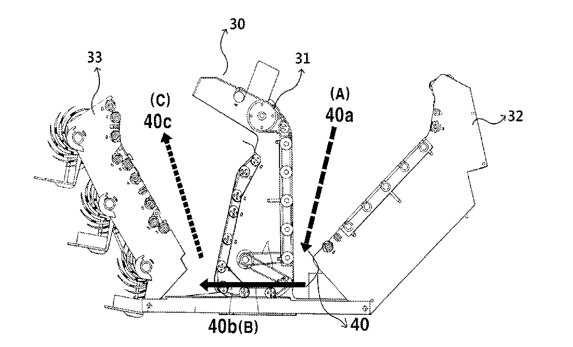
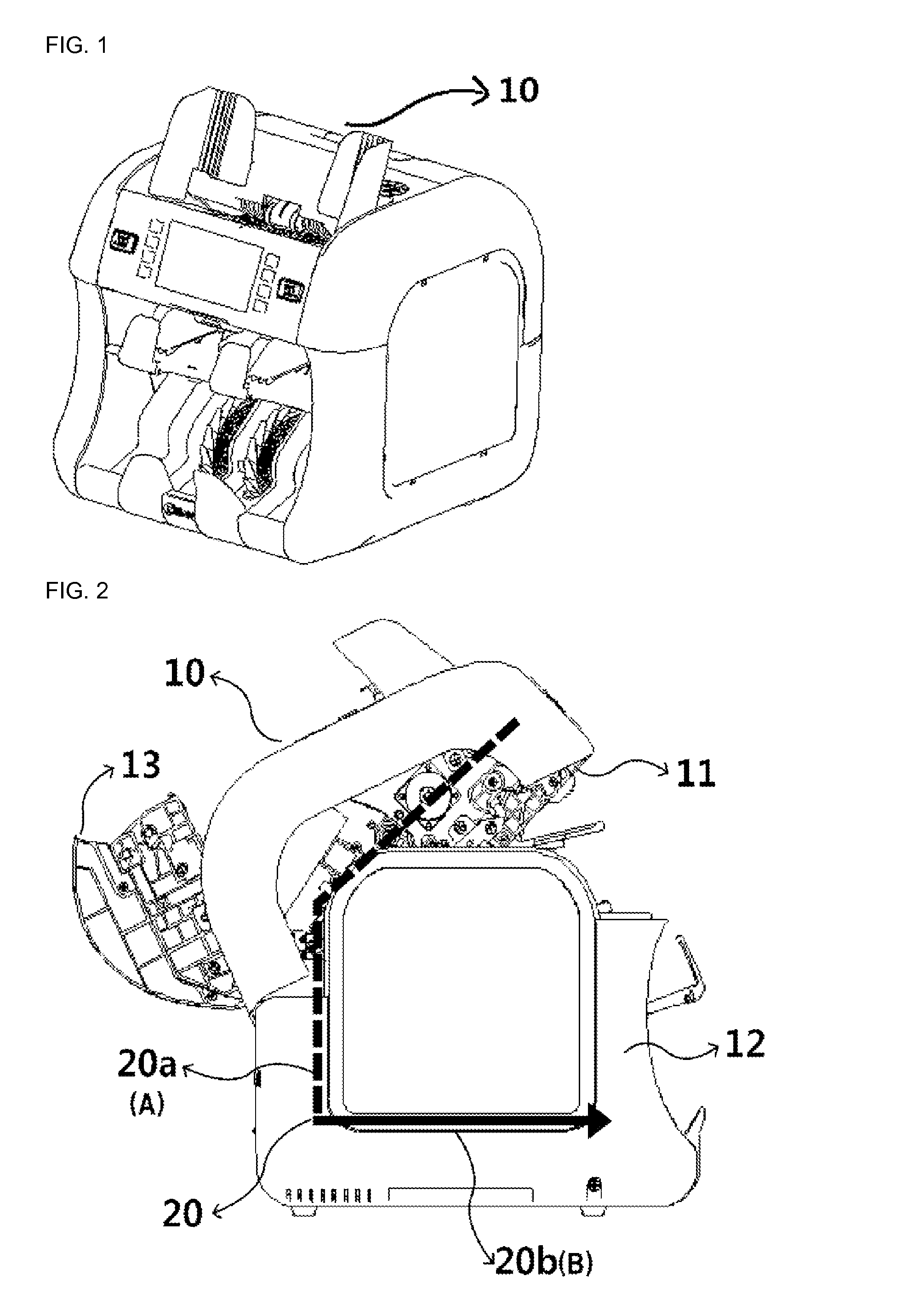
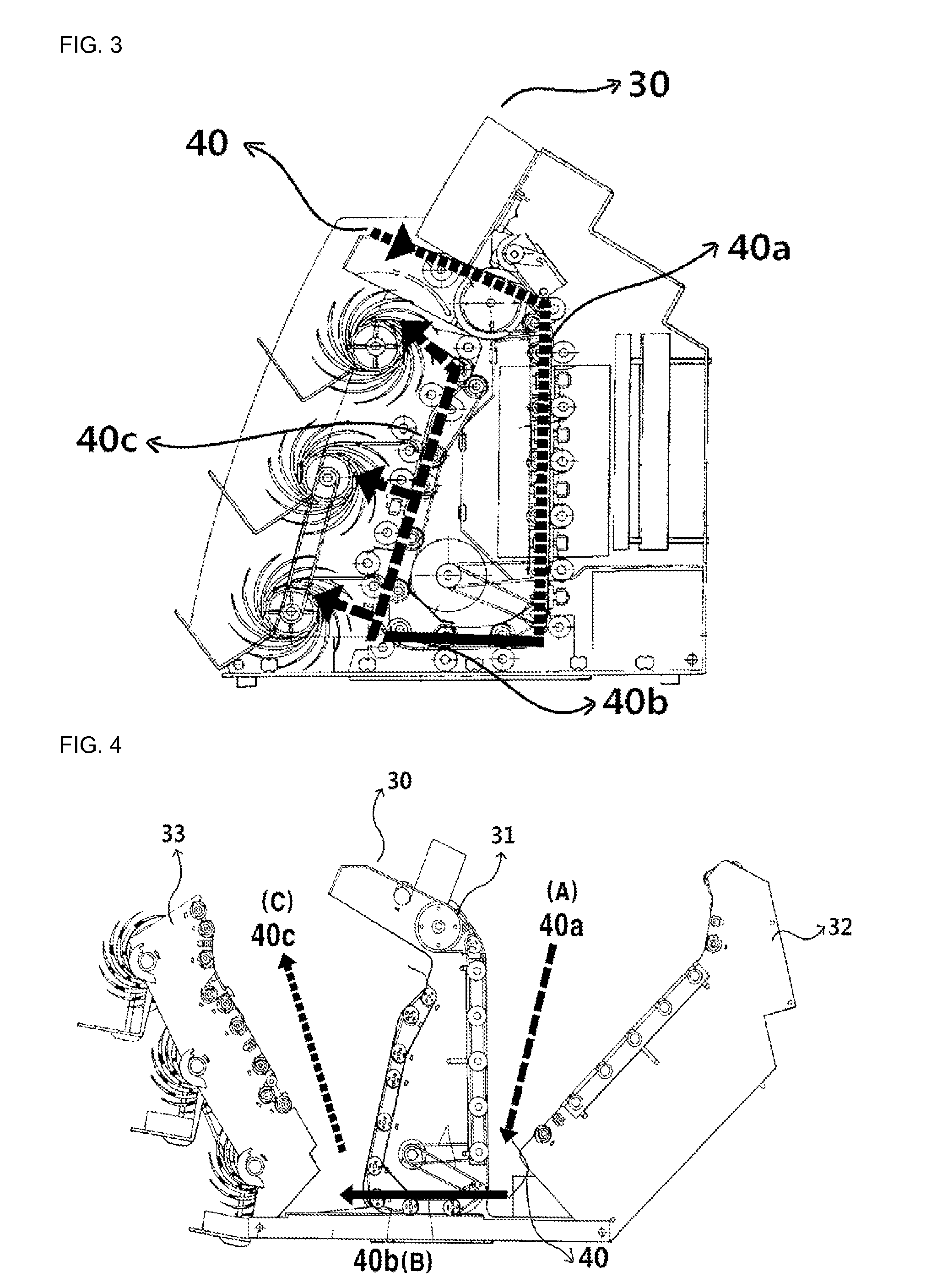
[0011]The purpose of the present invention is to provide a paper money processing apparatus to quickly and efficiently remove a jam of a paper money wherever the jam occurs on a transfer path by opening the whole transfer path of the paper money processing apparatus by one time opening operation when the paper money has jammed on the transfer path.

Means for Solving Objections

[0012]In order to achieve the purpose of the present invention, the paper money processing apparatus has a transfer path formed of three transfer path sections that can be entirely opened. Further, the paper money processing apparatus comprises a stationary main body part and other two parts that can be respectively decoupled from the stationary main body part, the stationary main body part and the other two parts being each other coupled by a link to interlock them, and decoupling of one part allowing to open the other parts by the interlocking in order to open the whole transfer path by ...


PUM


Abstract

The present invention relates to a paper money processing apparatus. In the paper money processing apparatus for sorting and counting paper money, the apparatus is divided into three parts in order for sections of a transfer path to open the whole transfer path. When jammed paper money is removed, portions separated from a fixed main body are linked with each other through links to remove the jammed paper money through only one operation.

Description

TECHNICAL FIELD[0001]The present invention relates to a paper money processing apparatus, and more particularly, to the paper money processing apparatus having the structure for quickly and efficiently removing a jam of a paper money by opening the whole transfer path of the paper money processing apparatus by one time opening operation when the paper money has jammed on a transfer path while the apparatus is processing the paper monies.BACKGROUND OF INVENTION[0002]FIG. 1 shows a perspective view of a conventional exemplary paper money processing apparatus 10 having one pocket structure, and FIG. 2 shows a side view representing the paper money processing apparatus 10 in the opened status to remove a paper money jammed on a transfer path 20 in the paper money processing apparatus 10 of the one pocket type.[0003]FIG. 3 shows a side view of a paper money processing apparatus 30 described in U.S. Patent Publication No. 6,772,886 as a prior art of the present invention, and FIG. 4 shows...

Claims


Application Information

Patent Timeline
Patent Type & Authority Applications(United States)
IPC IPC(8): G07D11/00
CPCG07D11/0039G07D11/0021G07D11/0084G07D11/16G07D11/237G07D11/50G07D11/10
Inventor JANG, SANG HWAN
Owner KISAN ELECTRONICS
Why Eureka
Try Eureka