Vehicle-mounted soil sampling apparatus

a soil sampling and vehicle-mounted technology, applied in the direction of instruments, wellbore/well accessories, agriculture, etc., can solve the problems of inability to know how much fertilizer or other additives to place at a soil plot, manual operation to perform soil sampling is necessary, tiresome and time-consuming, etc., to achieve convenient operation, easy maintenance, and low cost

Inactive Publication Date: 2015-02-17
AGRO ROYALTY CO
View PDF42 Cites 23 Cited by
  • Summary
  • Abstract
  • Description
  • Claims
  • Application Information

AI Technical Summary

Benefits of technology

[0017]It is therefore an object of the present invention to provide for a soil sampling mechanism that may collect soil samples over an area of interest without requiring a driver to exit the vehicle to which the sampling mechanism is attached.
[0018]It is also an object of the present invention to provide for a soil sampling mechanism that is inexpensive to produce and easy to maintain.
[0019]It is also an object of the present invention to provide for a soil sampling mechanism that allows for the pneumatic movement of collected samples from a collection tray to a location more convenient to an operator.
[0020]It is also an object of the present invention to provide for a soil sampling mechanism that allows the collection of a number of soil samples in a plurality of separate bags for later analysis.
[0021]It is also an object of the present invention to provide for a soil sampling mechanism that allows for the use of a computer-based mapping system in order to map an area of interest and collect samples from the appropriate portions of the area of interest.

Problems solved by technology

The grower cannot know how much fertilizer or other additives should be placed at a plot of soil, however, without knowing the current level of nutrients and important minerals that are already present in each plot.
Various hand tools have been developed to somewhat ease the burden of this task, but any manual operation to perform soil sampling is necessary tiresome and time-consuming because of the expanse of land that must be covered when soil sampling is performed as part of a large-scale commercial farming enterprise.
The result is a poor approximation of the optimal nutrient level for each plot of soil, since some plots will likely be under fertilized and others will be over fertilized.
Under fertilized plots will produce poor yields, and over fertilized plots may both produce poorer than optimum yields and also result in a waste of fertilizers.
The wasted fertilizer not only is an added expense for the grower, but also exacerbates environmental issues that may arise from the later run-off of the excessive fertilizer due to rain or wind.
The use of GPS in conjunction with manual soil sampling, however, only provides modest improvements in accuracy and efficiency.
The sampling mechanisms described above suffer from important disadvantages that have limited their adoption in large commercial farming operations.
Mechanisms that simply scoop a sample of material from the top of the ground are undesirable, since such a sample may not be representative of the lower levels of the soil in the area that is sampled.
A scooping mechanism will likely be unable to probe deeply enough to produce a sufficient sample to meet this need.
Although sampling mechanisms that insert a tube into the ground to collect a sample are superior to scoop mechanisms in many applications, the tube-type sampling mechanisms known in the art also suffer from important disadvantages.
The process of inserting and removing a tube from a moving vehicle presents a number of difficulties.
Depending upon the hardness of the soil, however, this may create a great deal of stress upon the tube.
While this may be a workable solution in very loose, highly compressible soil, this will likely lead to bending, excessive wear, or other damage to the tube in more firmly packed soil, such as many clay-based soils, or soil that may contain rocks or other hard obstacles.
While this arrangement may avoid the problems presented by tube rotation, the structure and linkages necessary for this functionality are complex, and would likely be expensive to manufacture and difficult to maintain.
The device is expensive, however, and while its use will likely prove to be cost-effective for larger farms, it is not clear that it will be cost-effective for small farms, where a more simple sampling scheme with fewer samples collected may suffice.

Method used


Image

  • Vehicle-mounted soil sampling apparatus
  • Vehicle-mounted soil sampling apparatus
  • Vehicle-mounted soil sampling apparatus

Examples


Embodiment Construction

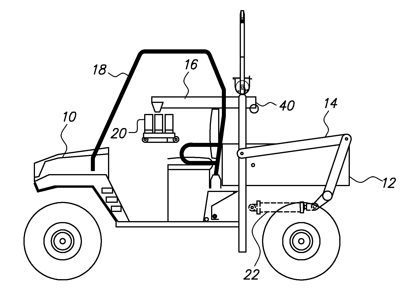
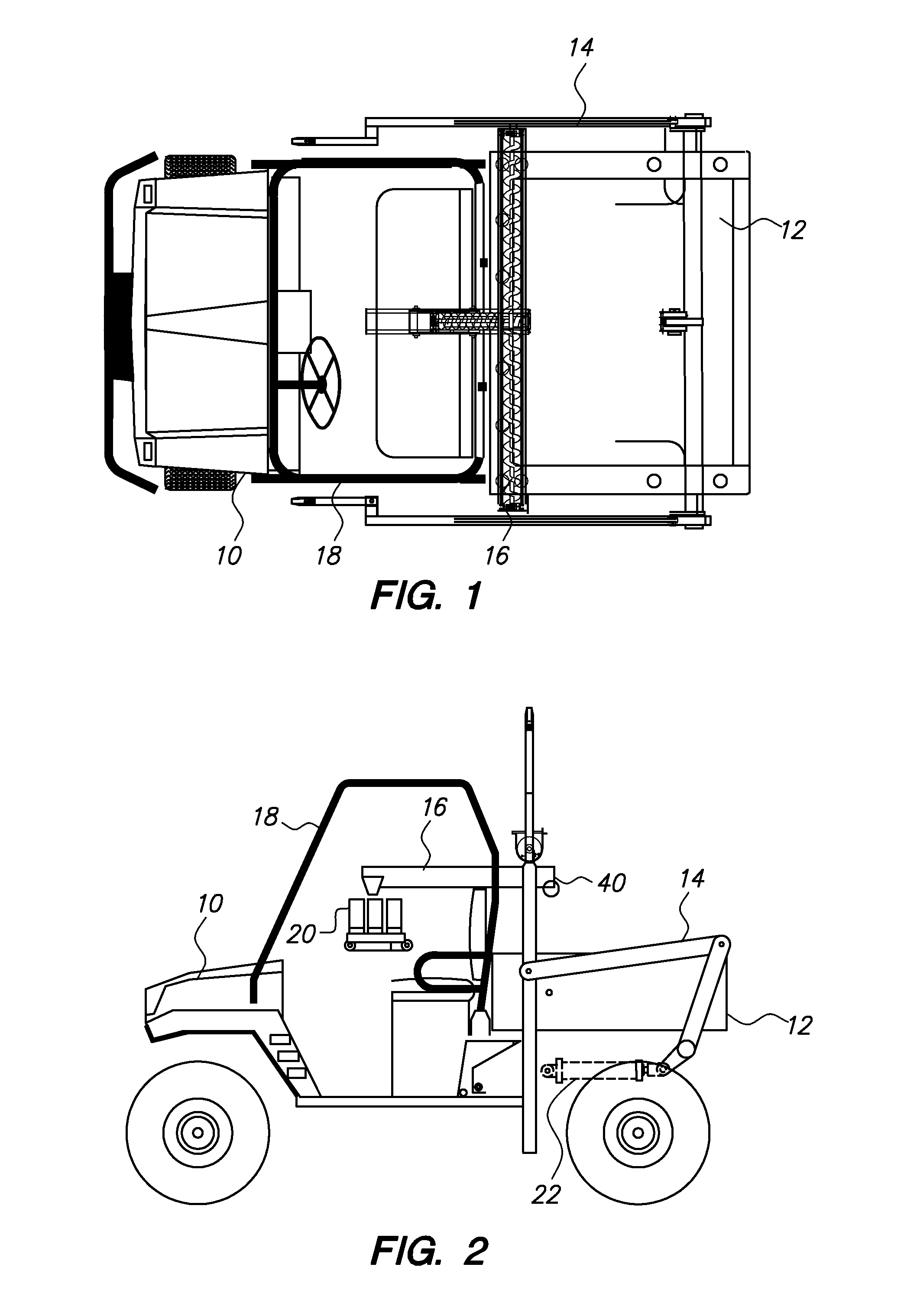
[0031]With reference to FIGS. 1 and 2, a general description of the preferred embodiment of the present invention may be described. Vehicle 10 may be a truck or any of the sorts of utility vehicles that are commonly used in farming applications. Preferably, vehicle 10 has a bed 12. Sampling assembly 14 and collection assembly 16, the individual components of which will be described in more detail below, are mounted at bed 12, and a portion of collection assembly 16 extends into cab 18 of vehicle 10. Bagging assembly 20 is preferably mounted in cab 18 in order to provide convenient access to collected soil samples for the driver of vehicle 10. Sampling assembly 14 is powered by hydraulic cylinders 22, of which there are two in the preferred embodiment.

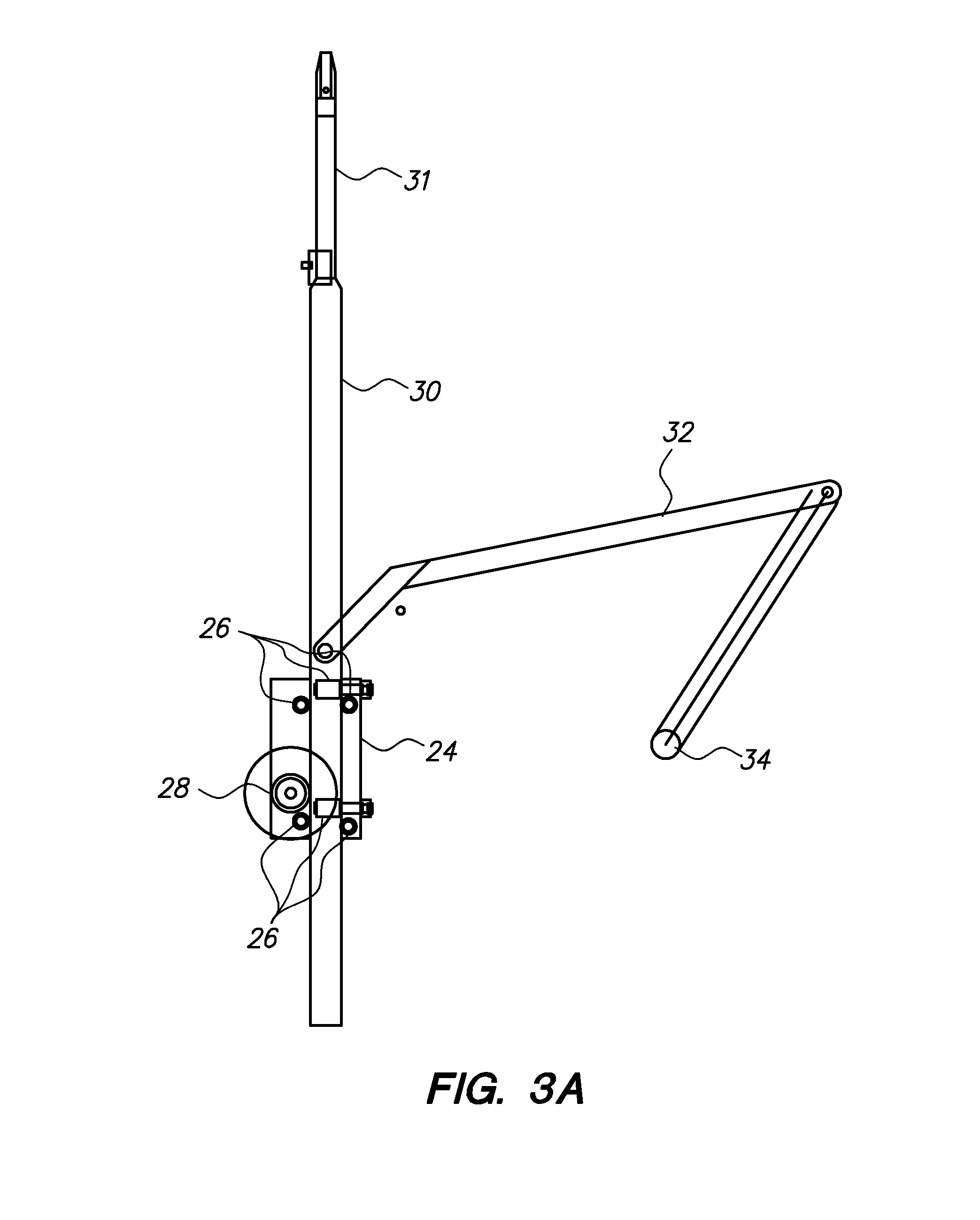
[0032]Turning now to FIGS. 3A and 3B, the probe components of sampling assembly 14 may be described in greater detail. It may be noted that the components shown in FIGS. 3A and 3B are repeated on each side of bed 12 of vehicle 10 in the...


PUM

PropertyMeasurementUnit
diameteraaaaaaaaaa
areaaaaaaaaaaa
speedaaaaaaaaaa

Abstract

A soil sampling apparatus comprising a motorized vehicle may be used to remove soil samples at intervals over a field of interest. The apparatus comprises a sampling assembly that rotates and extends downwardly into the soil to collect a sample. The probe assembly is raised to dump the sample into a collection assembly, which transfers the sample to a bagging assembly, where the sample may be bagged for later analysis.

Description

CROSS-REFERENCE TO RELATED APPLICATIONS[0001]This application claims the benefit of U.S. provisional patent application Ser. No. 61 / 321,425, filed on Apr. 6, 2010, and entitled “Vehicle-Mounted Soil Sampling Apparatus.” Such application is incorporated herein by reference in its entirety.STATEMENT REGARDING FEDERALLY SPONSORED RESEARCH OR DEVELOPMENT[0002]Not applicable.BACKGROUND OF THE INVENTION[0003]The present invention relates to soil sampling devices, and in particular to soil sampling devices that may be mounted on a truck, utility vehicle, or the like.[0004]In order to optimize the production capacity of any agricultural land, the grower must provide in each plot of soil the amount of fertilizers and other nutrients and additives that will render each plot ideal for the crop that is to be sewn and harvested. The grower cannot know how much fertilizer or other additives should be placed at a plot of soil, however, without knowing the current level of nutrients and important m...

Claims


Application Information

Patent Timeline
Patent Type & Authority Patents(United States)
IPC IPC(8): G01N1/08G01N1/38E21B49/02G01N1/34
CPCG01N1/08G01N1/04E21B7/027G01N33/24A01C21/007
Inventor BURTON, JAMES D.
Owner AGRO ROYALTY CO
Why Eureka
Try Eureka