Weight lifting device having selector device

a selector device and weight lifting technology, applied in the field of weight lifting devices, can solve the problems of weight members weight members also not being randomly secured or attached onto the handle, and weight members also not being randomly secured or attached to the handl

Inactive Publication Date: 2006-11-21
CHEN YAO NENG
View PDF11 Cites 71 Cited by
  • Summary
  • Abstract
  • Description
  • Claims
  • Application Information

AI Technical Summary

Benefits of technology

[0012]The weight member includes at least one peg attached thereto, the anchor plate includes at least one curved channel formed therein, to slidably receive the peg of the weight member, and to rotatably attach the anchor plate to the weight member. The peg of the weight member includes an enlarged head provided thereon, to engage with the anchor plate, and to retain the anchor plate to the weight member, and to prevent the anchor plate from being disengaged from the weight member.

Problems solved by technology

However, the closer or the inner weight members should first be selected and secured or attached onto the handle before the distal or the outer weight members are selectively secured or attached onto the handle, such that the weight members may not be randomly secured or attached onto the handle.
However, similarly, the closer or the inner weight members should first be selected and secured or attached onto the handle before the distal or the outer weight members are selectively secured or attached onto the handle, such that the weight members also may not be randomly secured or attached onto the handle.

Method used


Image

  • Weight lifting device having selector device
  • Weight lifting device having selector device
  • Weight lifting device having selector device

Examples


Embodiment Construction

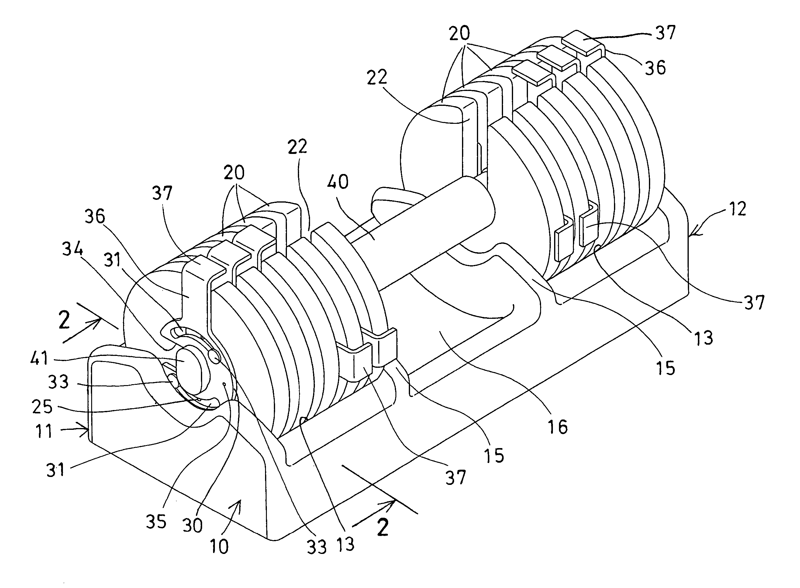
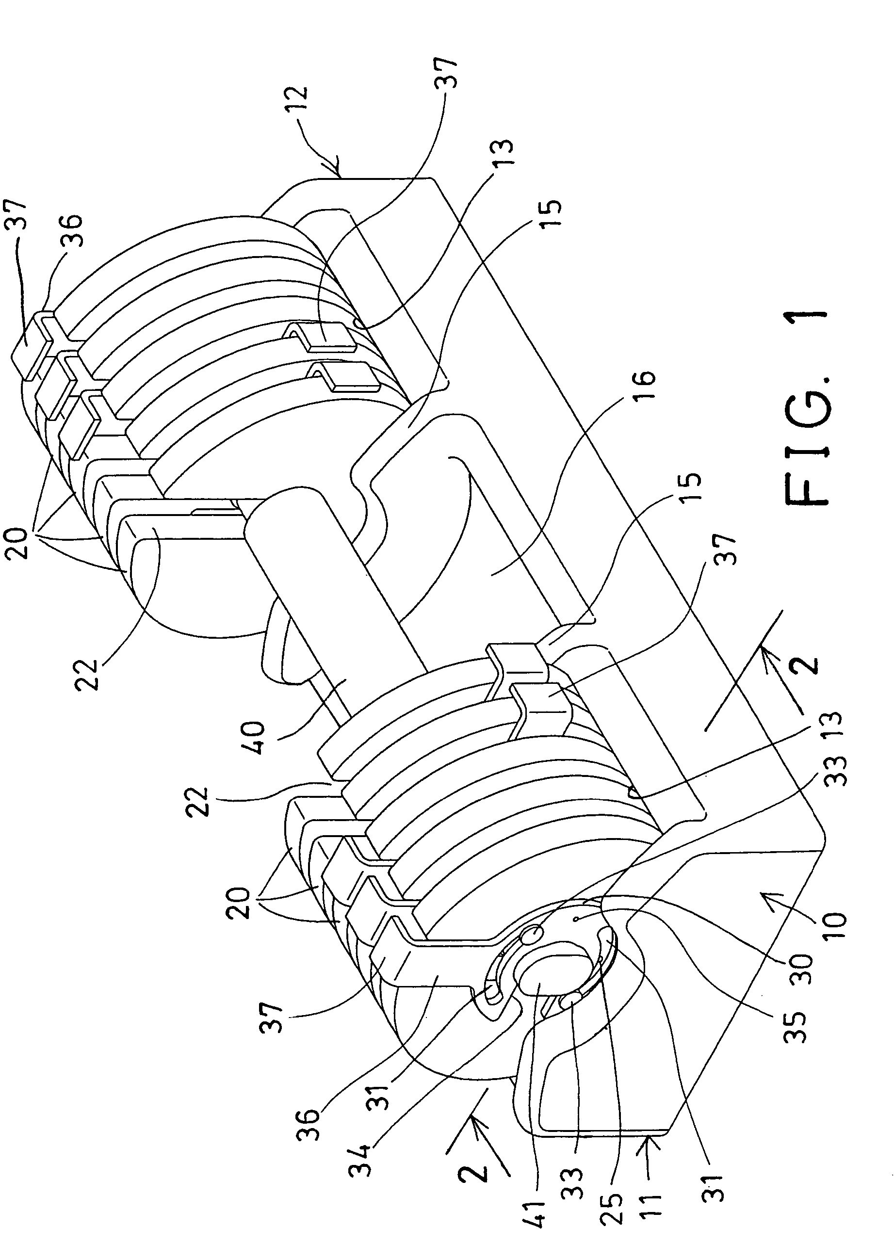
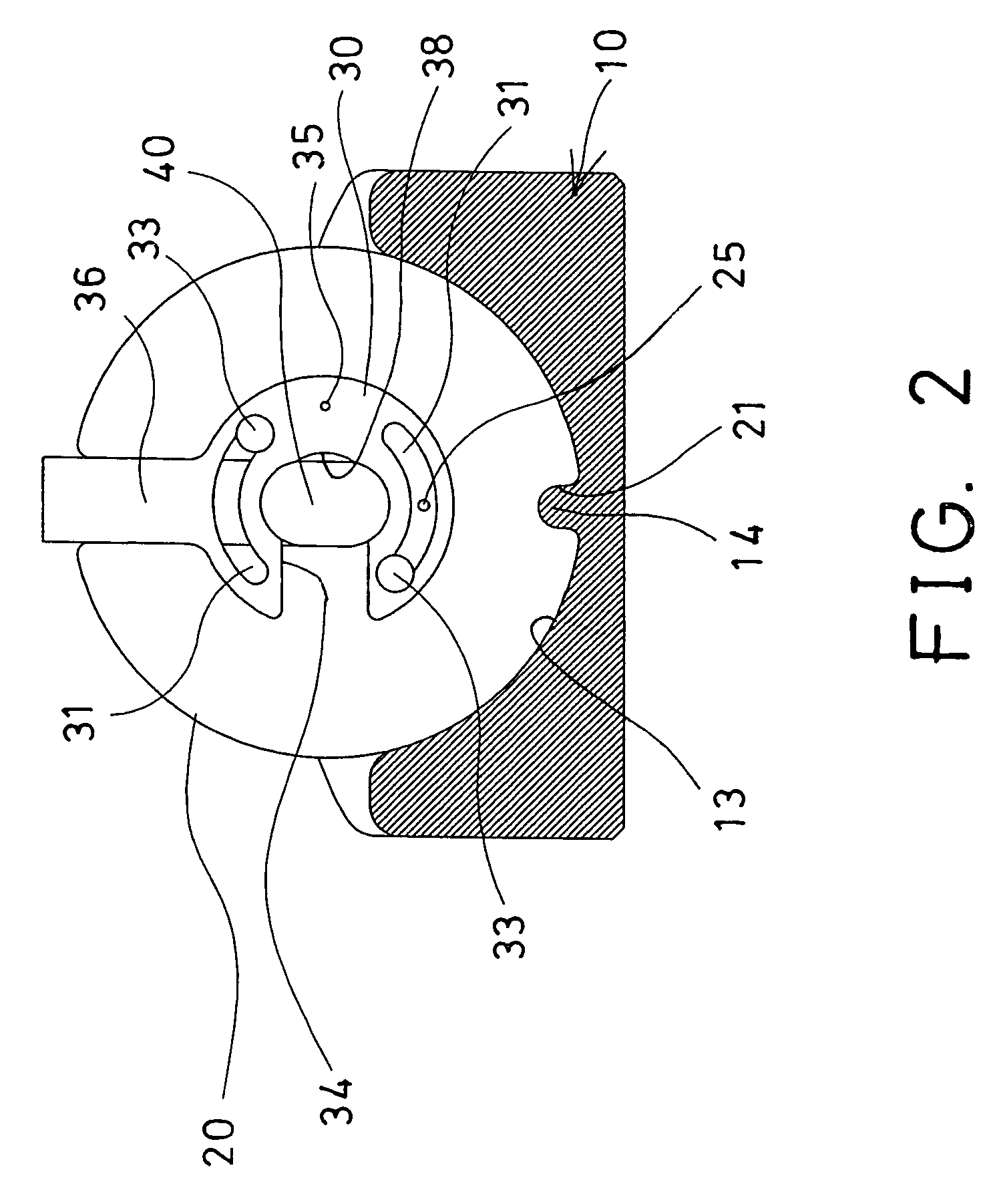
[0025]Referring to the drawings, and initially to FIGS. 1–3, a weight lifting device in accordance with the present invention comprises a base 10 including two side portions 11, 12 each having a number of curved depressions 13 formed therein (FIG. 2) for receiving weight members 20 respectively, and a number of projections 14 extended into the respective depressions 13 thereof (FIG. 2). The base 10 includes two partitions 15 extended or provided in the middle portion thereof, to form or define a recess 16 between the partitions 15.

[0026]Each of the weight members 20 includes an indentation 21 formed in the bottom thereof, to receive the corresponding projections 14 of the base 10, and thus to position the base 10 within the depressions 13 of the base 10. Each of the weight members 20 further includes a slot 22 formed in top thereof, extended from a center hole 28 (FIGS. 3, 4) to a perimeter of the associate weight members 20. The engagement of the projections 14 of the base 10 in th...


PUM


Abstract

A weight lifting device includes a handle having two end segments, a number of weight members each having a slot to receive either of the end segments of the handle, and an anchor plate rotatably attached to each of the weight members and having an opening selectively aligned with the slot of the weight member, to selectively receive either of the end segments of the handle. The anchor plate is rotatable relative to the weight member to offset the opening of the anchor plate from the slot of the weight member, and to selectively anchor the weight member to the handle. The desired number of weight members may thus be selectively attached to the handle.

Description

BACKGROUND OF THE INVENTION[0001]1. Field of the Invention[0002]The present invention relates to a weight lifting device, and more particularly to a weight lifting device having a selector device to randomly or selectively secure or anchor various numbers of weight members to the handle.[0003]2. Description of the Prior Art[0004]Various kinds of typical weight lifting devices or dumbbells have been developed and comprise a number of weight members to be adjustably secured or attached onto a handle, to allow the users to lift their own desired weights.[0005]For example, U.S. Pat. No. 5,839,997 to Roth et al. discloses one of the typical weight lifting devices or dumbbells comprising a rotatable shaft to select a desired number of weight members to the handle, without interrupting their exercise routine.[0006]However, the closer or the inner weight members should first be selected and secured or attached onto the handle before the distal or the outer weight members are selectively sec...

Claims


Application Information

Patent Timeline
Patent Type & Authority Patents(United States)
IPC IPC(8): A63B21/072A63B21/06A63B21/075
CPCA63B21/0728A63B21/075A63B21/00065
Inventor LIU, WEI MING
Owner CHEN YAO NENG
Why Eureka
Try Eureka