Handlebar shock absorbing system for bicycles

a technology for bicycles and handlebars, applied in the direction of steering devices, cycle equipments, mechanical devices, etc., can solve the problems of increasing the likelihood of some injuries, bicycle manufacturers don't readily progress to certain improvements, and cyclists still suffer injuries, etc., to improve the cycling comfort and minimize the effect of handlebar shock

Inactive Publication Date: 2006-12-12
YOU YEN JEN
View PDF11 Cites 4 Cited by
  • Summary
  • Abstract
  • Description
  • Claims
  • Application Information

AI Technical Summary

Benefits of technology

[0007]It is therefore an object of the present invention to minimized handlebar shock and to improve the cyclist's biking comfort.
[0008]Another object of the present invention is to allow flexible choices of spring force, based on the cyclist's riding habit and the length of handlebar grips, the spring force can be adjusted to his or her preference.
[0009]It is also an object of the present invention to allow various choices of the pull-up / push-down range of the handlebar grips, so cyclist can adjust the grips' pull-up / push-down range he or she enjoys most, for both forward and backward tilting handlebar grips
[0010]It is yet another object of the present invention to minimized cyclist's potential injury related to ridged handlebars.
[0014]The opposing side plates include two limiting bolts for contact of the torsion bracket. The top bolt limits the upward travel of the handlebar and a lower bolt limits the lower extent of the handlebar travel. The lower limiting bolt has an opposing slot, one on each side of the opposing side plates. The lower slot allows the adjustment of the allowable downward travel of the handlebar.
[0016]The substantially perpendicular handlebar grips are installed at certain angles on the handlebar and can be positioned at any angle as the cyclist may desire, from level, to up or down, or a forward tilting angle, to increase cyclist's comfort. As well the rotation of the handlebar against the torsion spring will absorb much of the bicycle's shock to minimize the negative impact to a cyclist's wrists, elbows, shoulders and body.

Problems solved by technology

Although, the above solutions do achieve some shock-absorbing effect, cyclists still suffer injuries.
When shock occurs on an uneven road, the cyclist generally grips more firmly which can increase the likelihood of some injuries.
The fixed link between the handlebar and the handlebar stem seems to be one of the main causes of certain injuries.
Bicycles are a multiple-purpose vehicle for transportation, sports, and recreational activities and consumers and thus bicycle manufacturers don't readily progress to certain improvements, unless these improvements are more variably adaptable.

Method used


Image

  • Handlebar shock absorbing system for bicycles
  • Handlebar shock absorbing system for bicycles
  • Handlebar shock absorbing system for bicycles

Examples


Embodiment Construction

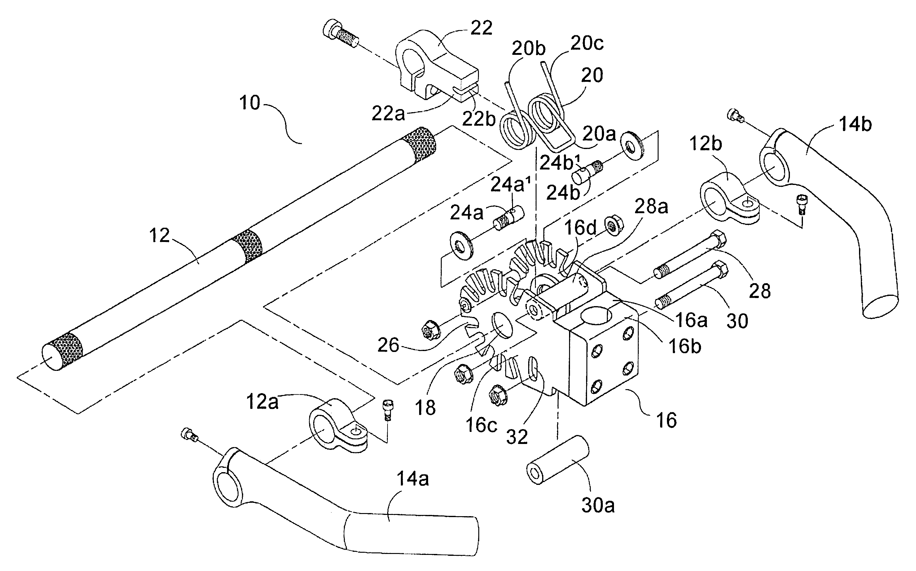
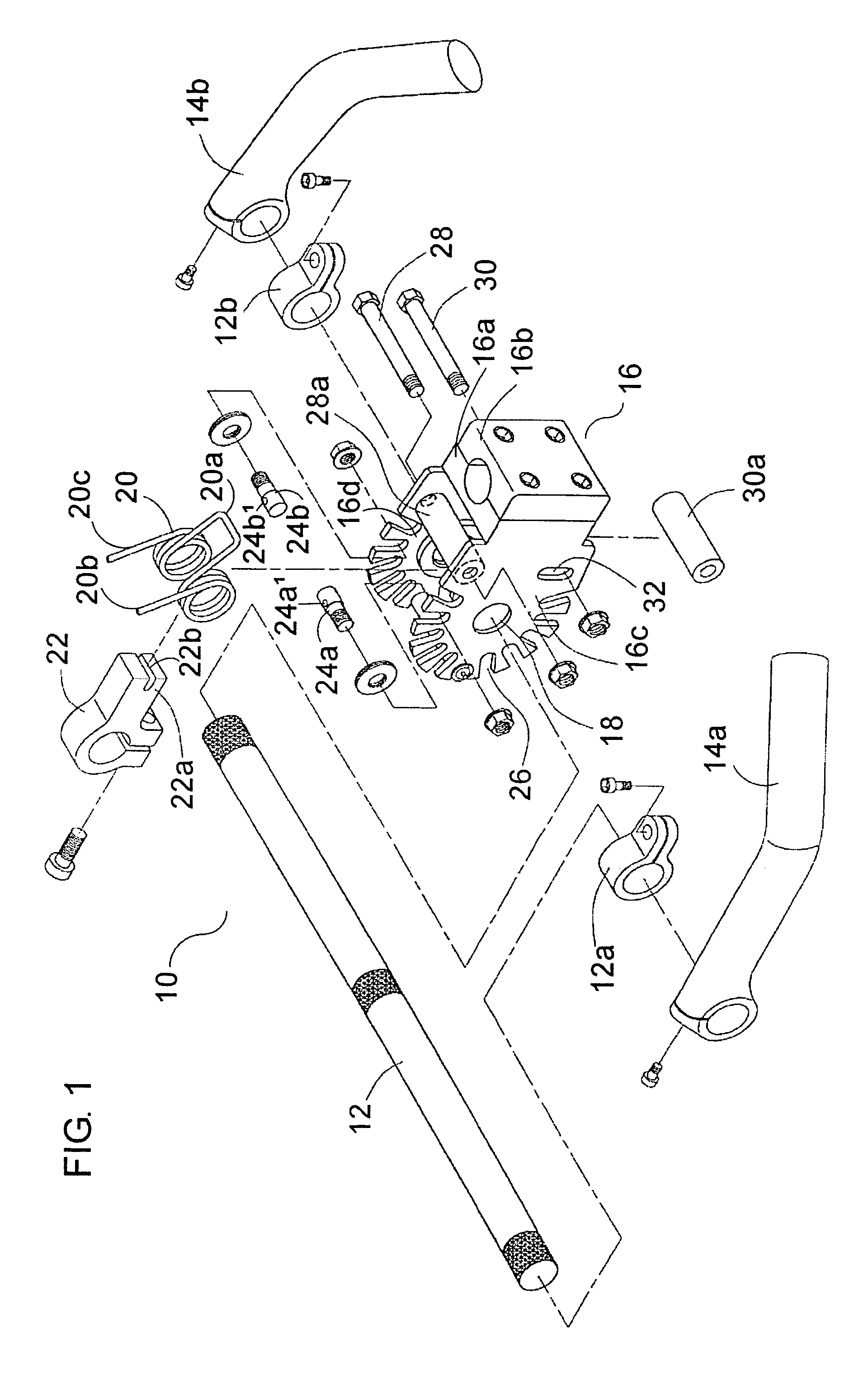
[0034]The handlebar shock-absorbing system is generally referred to as 10. As shown in FIG. 1 in exploded schematic view, one embodiment of the handlebar shock-absorbing system 10 includes a handlebar 12, a pair of handlebar grips 14a and 14b, and a handlebar stem mounting bracket 16. The handlebar mounting bracket 16 has a split mounting block 16a and 16b so as to be easily mounted onto a handlebar stem.

[0035]Handlebar 12 is pivotally or rotatably mounted to handlebar mounting bracket 16 through apertures 18, one in each of two opposing parallel mounting plates 16c and 16d extending forwardly from handlebar mounting bracket 16. Torsion spring 20 is mounted between opposing mounting plates 16a and 16b. In embodiments where torsion spring 20 is a helical coil spring, the spring is aligned and sized so as to slide over handlebar 12 when handlebar 12 is mounted through apertures 18. Cross-member 17 is mounted between the distal ends of mounting plates 16c and 16d.

[0036]A handlebar tor...


PUM


Abstract

A handlebar shock absorbing system for bicycles, utilizing a pair of side plates attached to a handlebar mounting bracket with rotational movement of a handlebar against a torsional spring. Where the handlebar can be adjustable for torsional spring force and / or for rotational travel and positioning of handlebar grips, either forward tilting, level or rearward tilting.

Description

FIELD OF THE INVENTION[0001]The invention relates to a bicycle handlebar mounting system, and more specifically to a variably adjustable shock-absorbing handlebar mounting system utilizes an adjustable torsional spring force.BACKGROUND OF THE INVENTION[0002]In order to reduce shock and help prevent injuries, currently the bicycle industry has been providing a number of solutions, such as springs or liquid type shock-absorber within the front fork, springs installed under the seat, shock-absorber and springs installed under the upper frame tube. Although, the above solutions do achieve some shock-absorbing effect, cyclists still suffer injuries.[0003]When shock occurs on an uneven road, the cyclist generally grips more firmly which can increase the likelihood of some injuries. The fixed link between the handlebar and the handlebar stem seems to be one of the main causes of certain injuries. By making the present invention much more adjustable for various types of cycling and a wide r...

Claims


Application Information

Patent Timeline
Patent Type & Authority Patents(United States)
IPC IPC(8): B62K21/20
CPCB62K21/14Y10T74/20786Y10T74/2078
Inventor YOU, YEN-JEN
Owner YOU YEN JEN
Why Eureka
Try Eureka