Wireless danger proximity warning system and method

a proximity warning and wireless technology, applied in traffic control systems, transportation and packaging, instruments, etc., can solve the problems of 200,000 passive railroad crossings, inability to detect danger,

Inactive Publication Date: 2006-12-12
HUMATICS CORP
View PDF10 Cites 115 Cited by
  • Summary
  • Abstract
  • Description
  • Claims
  • Application Information

AI Technical Summary

Problems solved by technology

For example, traditional railroad collision avoidance systems are inadequate.
This means that over 200,000 railroad crossings are passive railroad crossings, which are particularly dangerous since they have no warning lights or retractable gates to warn a motorist that a locomotive is approaching the railroad crossing.
Even with the use of conventional railroad collision avoidance systems at the active railroad crossings and the lack of collision avoidance systems at passive railroad crossings there is still an unacceptable number of train-vehicle accidents.
Unfortunately, the wireless railroad grade crossing motorist warning system uses conventional radio communication technology and as such suffers from the traditional problems associated with that technology including, for example, interference from other radios, high power consumption and multipath interference.
While this system is an improvement over many others it is still subject to interference from other transmitters and must operate within an assigned frequency that can be adversely affected by different types of interference commonly associated with traditional communication technology.

Method used


Image

  • Wireless danger proximity warning system and method
  • Wireless danger proximity warning system and method
  • Wireless danger proximity warning system and method

Examples


first embodiment

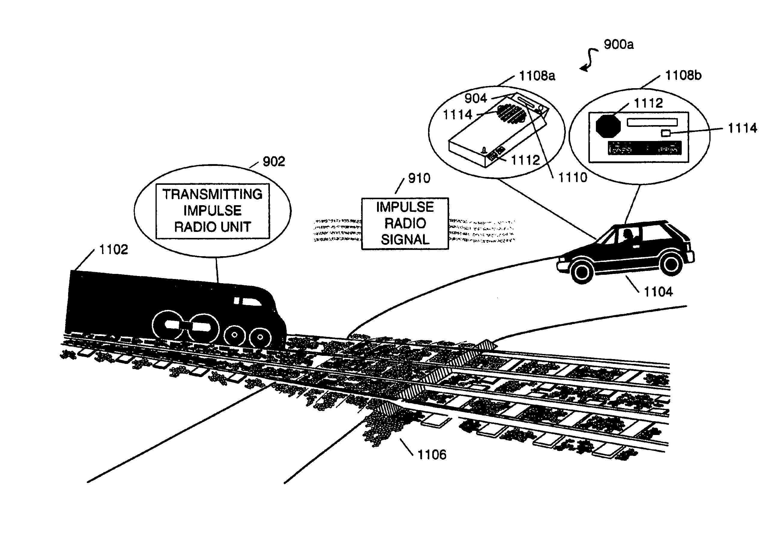
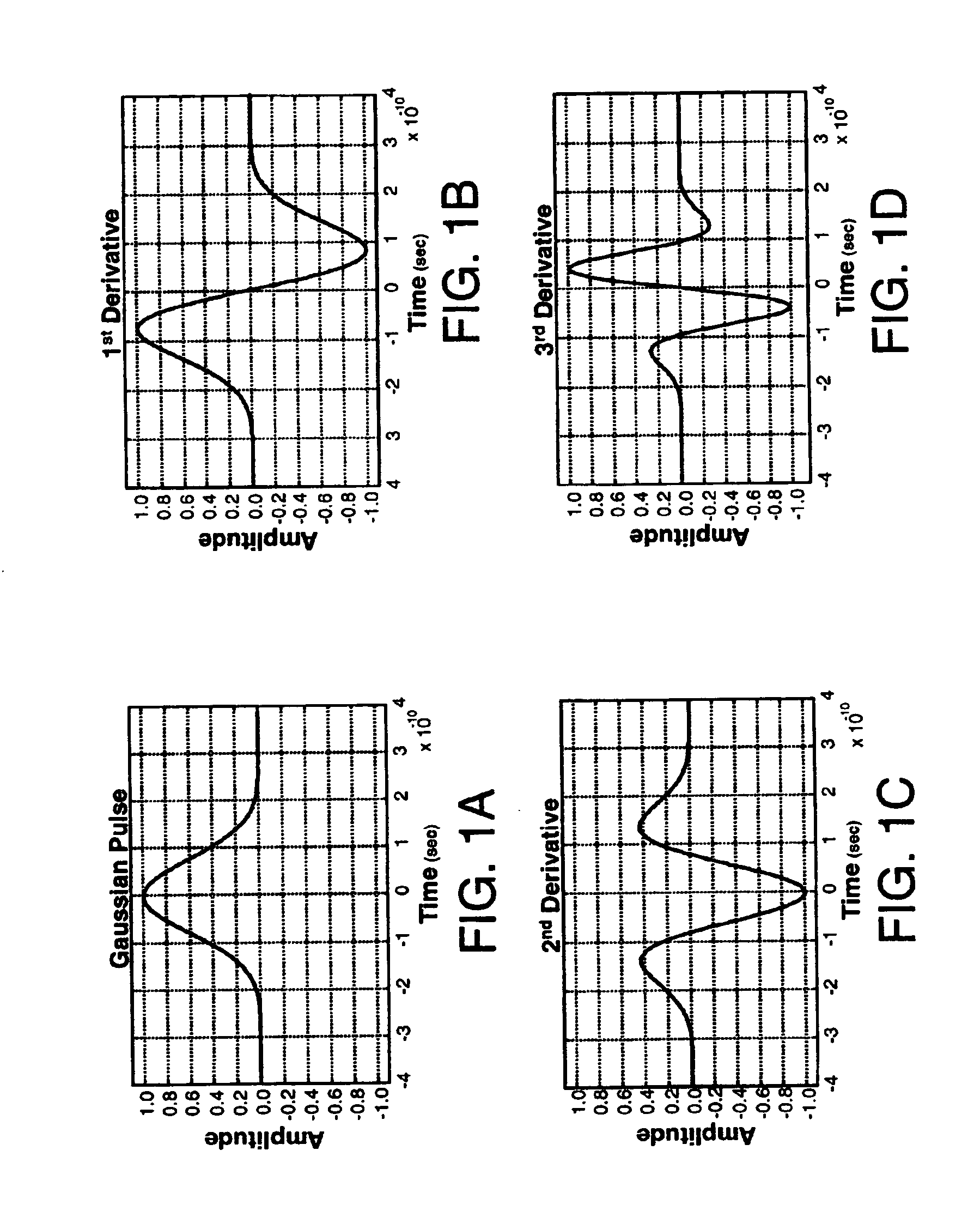
[0150]Referring to FIGS. 11 and 12, there are diagrams illustrating in greater detail the components and steps of the danger proximity warning system 900a and method 1000a. In this embodiment, the danger proximity warning system 900 includes a transmitting impulse radio unit 902 coupled (step 1202) to a first object such as locomotive 1102 and a receiving impulse radio unit 904 coupled (step 1204) to a second object such as vehicle 1104 (shown as a car). The transmitting impulse radio unit 902 operates to transmit (step 1206) an impulse radio signal 910 having a known pseudorandom sequence of pulses that look like a series of Gaussian waveforms (see FIGS. 1–3) towards the receiving impulse radio unit 904 attached to the second object (e.g., vehicle 1104). In particular, the transmitting impulse radio unit 902 may continually transmit the impulse radio signal 910 or it may transmit the impulse radio signal 910 whenever an alert condition is met such as when a whistle on the locomotiv...

second embodiment

[0153]Referring to FIGS. 13 and 14, there are diagrams illustrating in greater detail the components and steps of the danger proximity warning system 900b and method 1000b. In this embodiment, the danger proximity warning system 900b includes a transmitting impulse radio unit 902 coupled (step 1402) to a first object such as locomotive 1102 and a receiving impulse radio unit 904 coupled (step 1404) to a second object such as an active railroad pole 1302. The transmitting impulse radio unit 902 operates to transmit (step 1406) an impulse radio signal 910 having a known pseudorandom sequence of pulses that look like a series of Gaussian waveforms (see FIGS. 1–3) towards the receiving impulse radio unit 904 attached to the second object (e.g., railroad pole 1302 of which two are shown). In particular, the transmitting impulse radio unit 902 may continually transmit the impulse radio signal 910 or it may transmit the impulse radio signal 910 whenever a alert condition is met such as whe...

third embodiment

[0156]Referring to FIGS. 15 and 16, there are diagrams illustrating in greater detail the components and steps of the danger proximity warning system 900c and method 1000c. In this embodiment, the danger proximity warning system 900c includes a transmitting impulse radio unit 902 coupled (step 1602) to a first object such as control box 1502 and a receiving impulse radio unit 904 coupled (step 1604) to a second object such as vehicle 1104. The control box 1502 is located in a monitoring location such as next to railroad tracks 1504 and is capable of using a sensor 1506 (e.g., electromagnetic sensor, motion detector, percussion sensor) to sense the presence of a third object (e.g., locomotive 1102). Moreover, the control box 1502 can be powered by a variety of power sources including, for example, a solar battery or a power line.

[0157]The transmitting impulse radio unit 902 operates to transmit an impulse radio signal 910 having a known pseudorandom sequence of pulses that look like ...


PUM


Abstract

A danger proximity warning system and method are disclosed that utilize ultra wideband (UWB) technology to effectively warn a person when there is a potentially dangerous situation in their vicinity. In one embodiment, the danger proximity warning system includes a transmitting UWB radio coupled to a first object and a receiving impulse radio unit coupled to a second object. The transmitting impulse radio unit operates to transmit an UWB signal towards the second object when the first object is a predetermined distance away. Upon receiving the UWB signal, the receiving UWB radio makes sure a person associated with the second object is informed about the potentially dangerous situation. Several embodiments of the danger proximity warning system and method are disclosed all of which operate to warn a person when there is a potentially dangerous situation in their vicinity.

Description

CROSS REFERENCE TO RELATED APPLICATION[0001]This application is a continuation-in-part application of U.S. patent application Ser. No. 10 / 753,891 filed Jan. 8, 2004, now U.S. Pat. No. 6,917,284, issued Jul. 12, 2005, which is a continuation application of U.S. patent application Ser. No. 09 / 960,820, filed Sep. 21, 2001, now U.S. Pat. No. 6,759,948, issued Jul. 6, 2004.BACKGROUND OF THE INVENTION[0002]1. Field of the Invention[0003]The present invention generally relates to the danger proximity warning field and, in particular, to a wireless danger proximity warning system and method.[0004]2. Description of Related Art[0005]When it comes to public safety and personal safety, it is always desirable to improve upon the way people are warned about potentially dangerous situations. For example, traditional railroad collision avoidance systems are inadequate. Presently, there are approximately 259,000 railroad crossings in the United States of which approximately 22% are active railroad c...

Claims


Application Information

Patent Timeline
Patent Type & Authority Patents(United States)
IPC IPC(8): B60Q1/00B60Q1/52B61L23/06B61L29/24G08G1/16
CPCB60Q9/008B61L23/06B61L29/24G08G1/161
Inventor GRISHAM, WILLIAM T.ROBERTS, MARK D.
Owner HUMATICS CORP
Why Eureka
Try Eureka