Gold club with customizable alignment sighting and weighting device

a weighting device and alignment sighting technology, applied in the field of golf club alignment sighting and weighting device, can solve the problems of user inconvenience or burden, and achieve the effects of reducing the amount of intrusion or interference, facilitating adjustment, and accurate alignment sighting

Inactive Publication Date: 2007-03-06
NAGY LAJOS I
View PDF22 Cites 53 Cited by
  • Summary
  • Abstract
  • Description
  • Claims
  • Application Information

AI Technical Summary

Benefits of technology

[0005]Accordingly, it is a principal object of the present invention to provide a golf club alignment sighting device which can be attached to different types of golf clubs and adjusted for alignments for different individual factors or preferences of golfers. It is a further object of the invention to provide a device which provides accurate alignment sighting, while also providing an indication of the direction of misalignment. Another object is for the device to be easy to adjust, and to present a minimum of intrusion or interference when attached to the golf club. It is another object that the sighting device can allow adjustment of the club head's weighting (moment of inertia).
[0008]sighting means carried on the mounting means in an adjustable sighting position for providing the user a visual target indicator of desired alignment of the club head (and shaft) with the user's line of sight to the sighting means; and
[0009]adjusting means carried on the mounting means for adjusting the sighting position of the sighting means so that the user can adjust the sighting means to provide the visual indicator of desired alignment according to the user's individual alignment factors and preferences.
[0012]In a third embodiment for a putter, the spherical body (as in the second embodiment) is mounted with an interference fit in a mounting cup, and the cup is mounted on a putter using a flange, threaded end, or bracket. To provide the interference fit, the spherical body has axially split sides that can be expanded outward when an expansion plug threaded into the bottom of the hollow tube is turned with a hex wrench inserted through the tube opening. Expansion of the split sides allows the spherical body to be retained tightly in a desired angular position in the mounting cup.

Problems solved by technology

Golf is an excruciating game in which small misalignments of the golfer's posture, hand position, and club position at address of the ball relative to the target can be greatly magnified into an unwanted result.
However, these generally are assembled or fabricated with the alignment sighting component in a fixed position which cannot be varied despite different individual factors or preferences of golfers.
Other types of alignment sighting devices used for other clubs include sighting rods that attach to the club shaft and may be adjusted to individual preferences, but these have the problem that they are bulky or intrusive for the user when positioned on the shaft.

Method used


Image

  • Gold club with customizable alignment sighting and weighting device
  • Gold club with customizable alignment sighting and weighting device
  • Gold club with customizable alignment sighting and weighting device

Examples


first embodiment

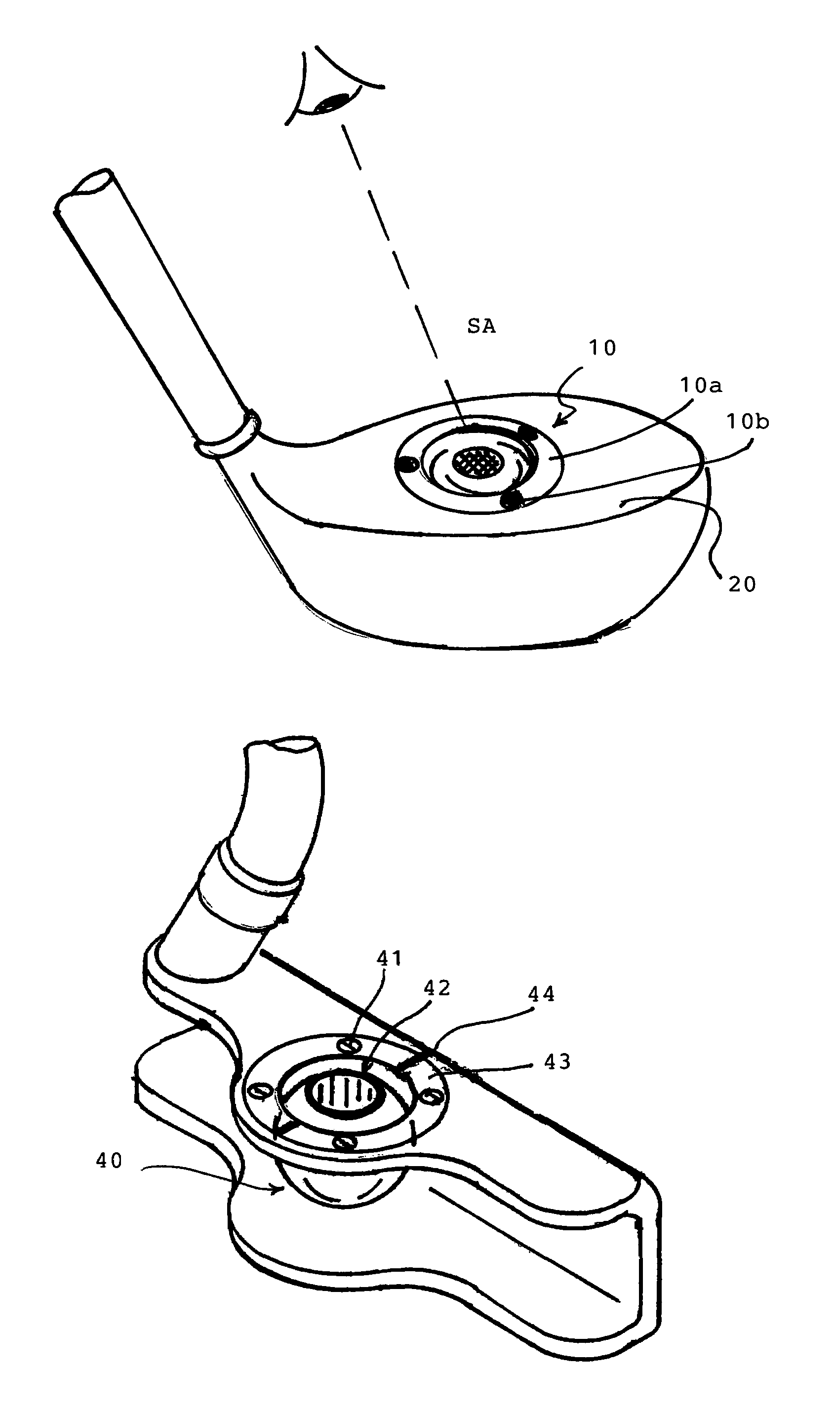
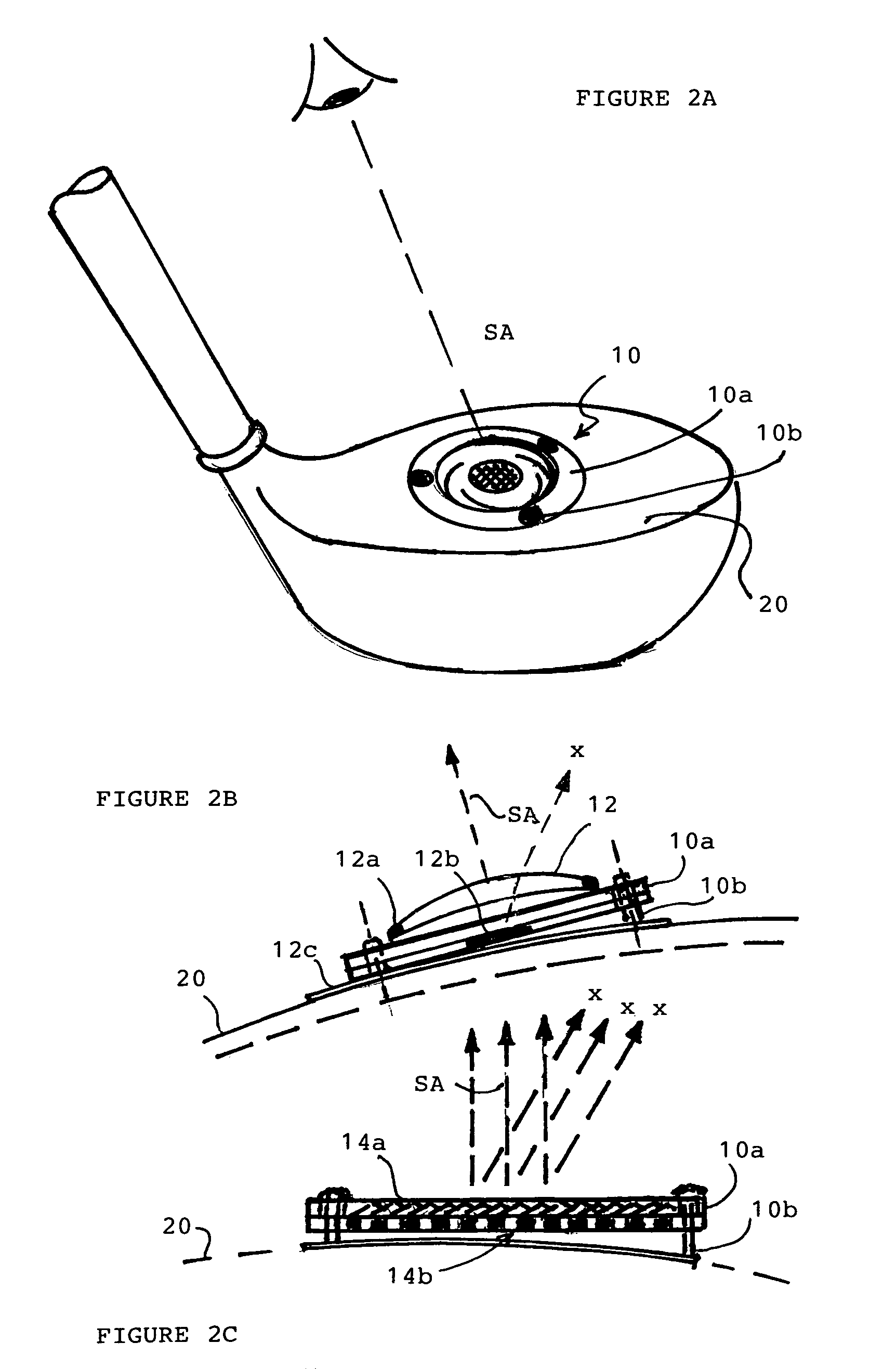
[0028]In FIG. 2A, the golf club alignment sighting device of the present invention is shaped as a planar disc 10 that is mounted on the upper surface 20 of the head of a golf club. The disc has a number (3 or more) of leveling posts 10b spaced around a peripheral rim or ring 10a. By adjusting the leveling posts 10b, the sighting axis SA of the device can be adjusted three dimensionally to a sighting position that is in the preferred alignment position with the eyes of the user. If the user takes up a posture, grip, or stance that results in the user's head (eyes) being out of alignment with the sighting axis SA, the device 10 will not provide the desired target indicator, but would instead provide an indication that the user is not in alignment.

[0029]In FIG. 2B, one version of the planar disc embodiment is shown having a concave lens element 12 mounted on the peripheral ring 10a concentric with the sighting axis SA of the device. The lens element 12 can be adhered by epoxy or other ...

second embodiment

[0034]In FIGS. 4A–4C, the device is shown, designed for a putter. The device is formed in a spherical shape 40 mounted between upper and lower horizontal flanges of the putter head, and clamped in position with an annular collar 43 retained by threaded screw fasteners 41. The spherical device 40 can be made of a medium-hard plastic or dense rubber material, so as to provide a friction holding force when clamped by the collar 43 against the bottom flange of the putter. An annular opening 42 at its top-facing side leads into a hollow tube aligned with the sighting axis SA extending into the spherical body. The bottom plane or shoulder 42a of the tube has a contrasting color or texture imprinted thereon that serves as an inner circle of the target indicator. A color-contrasting edge is imprinted or decal is adhered around the annular opening 42 to serve as an outer circle of the target indicator. The desired target indicator of concentric circles is provided when the user's line of sig...

fifth embodiment

[0039]In a fifth embodiment, the alignment sighting device is designed for use in a driver or wood and is combined with a weighting element that allows for adjustment of the club's moment of inertia. In FIG. 8A, an explanation is provided how weight distribution in a driver or wood affects the moment of inertia of the club. In laymen's terms, the moment of inertia (MOI) is a measure of resistance to twisting. MOI is increased by shifting weight distribution as far as possible away from the axis of rotation. The typical driver has a vertical head axis of rotation A, a lengthwise head axis of rotation B, and a sidewards head axis of rotation C, as well as a shaft axis of rotation D. A large head design with high MOI can increase the resistance to twisting around the shaft axis D, which can make it harder to square the club face. To reduce the shaft MOI, it may be desirable to shift some weight to move the center of gravity (checkered ball in the figure) closer to the shaft. In other s...


PUM


Abstract

A customizable alignment sighting device for a golf club is mounted to an upper surface of the head of the golf club with a sighting element providing the user a visual target indicator for desired alignment of the club head with the user's line of sight. The sighting element can be readily adjusted for the user's preferences. When not aligned, the sighting element provides an indication of the magnitude and direction of misalignment. In one embodiment, the device is shaped as a planar disc mounted on the upper surface of the club head by leveling posts spaced around its periphery. The sighting element is a concave lens or lenticulated grid or grill superimposed on a target image. In another embodiment, the device has a 3D device body mounted in a mounting cup or socket fastened to or formed in the head of the golf club. The device body has a larger-diameter circle marked around an annular opening, and a smaller-diameter circle marked depthwise inside the opening in the device body to provide a target of concentric circles by parallax effect. The device body can be formed as a sphere with axially split sides that are expanded outward when an expansion plug is threaded in the bottom, providing an interference fit holding it in position in the mounting cup. The spherical body can be formed with 4 alignment sighting holes at 90° intervals around a vertical plane and provided with a weighting element fixed at an offset position, such that it can be rotated to use any of the different alignment holes for adjusting the weight distribution in the club head.

Description

TECHNICAL FIELD[0001]This invention generally relates to a golf club alignment sighting and weighting device, and more particularly, to one that provides an accurate sighting function for the user by attachment on the golf club itself with a minimum of intrusion or interference.BACKGROUND OF INVENTION[0002]Golf is an excruciating game in which small misalignments of the golfer's posture, hand position, and club position at address of the ball relative to the target can be greatly magnified into an unwanted result. All players strive for ever more consistency in alignment at address and execution of a swing which will deliver an accurate stroke. Referring to FIG. 1, the general objective of proper alignment is to position the head (eyes) of the golfer along a vertical line VV bisecting the golfer's stance, the feet along a horizontal line HH aimed toward the target, and the golfer's center of gravity over the feet so as not to lean too far forward or back in the stance. The club head...

Claims


Application Information

Patent Timeline
Patent Type & Authority Patents(United States)
IPC IPC(8): A63B69/36A63B53/08
CPCA63B53/04A63B53/0466A63B53/0487A63B69/3632A63B53/047A63B69/3685A63B2053/0437A63B2053/0441A63B2053/0491A63B60/02A63B60/46A63B53/0437A63B53/0441A63B60/00
Inventor NAGY, LAJOS I.
Owner NAGY LAJOS I
Why Eureka
Try Eureka