Decorative lamp cover

Inactive Publication Date: 2007-03-13
FUNG DUNCAN C
View PDF3 Cites 13 Cited by
  • Summary
  • Abstract
  • Description
  • Claims
  • Application Information

AI Technical Summary

Benefits of technology

[0007]It is therefore an object of the present invention to provide a durable and highly decorative lamp cover for, for example, exterior lighting devices

Problems solved by technology

Such prior art devices are, largely because of their materials of fabrication, not sufficiently weather, UV, etc. resistant as to be satisfactorily used more than about one season before disposal.
Additionally, because of their design to surround th

Method used


Image

  • Decorative lamp cover
  • Decorative lamp cover
  • Decorative lamp cover

Examples


Embodiment Construction

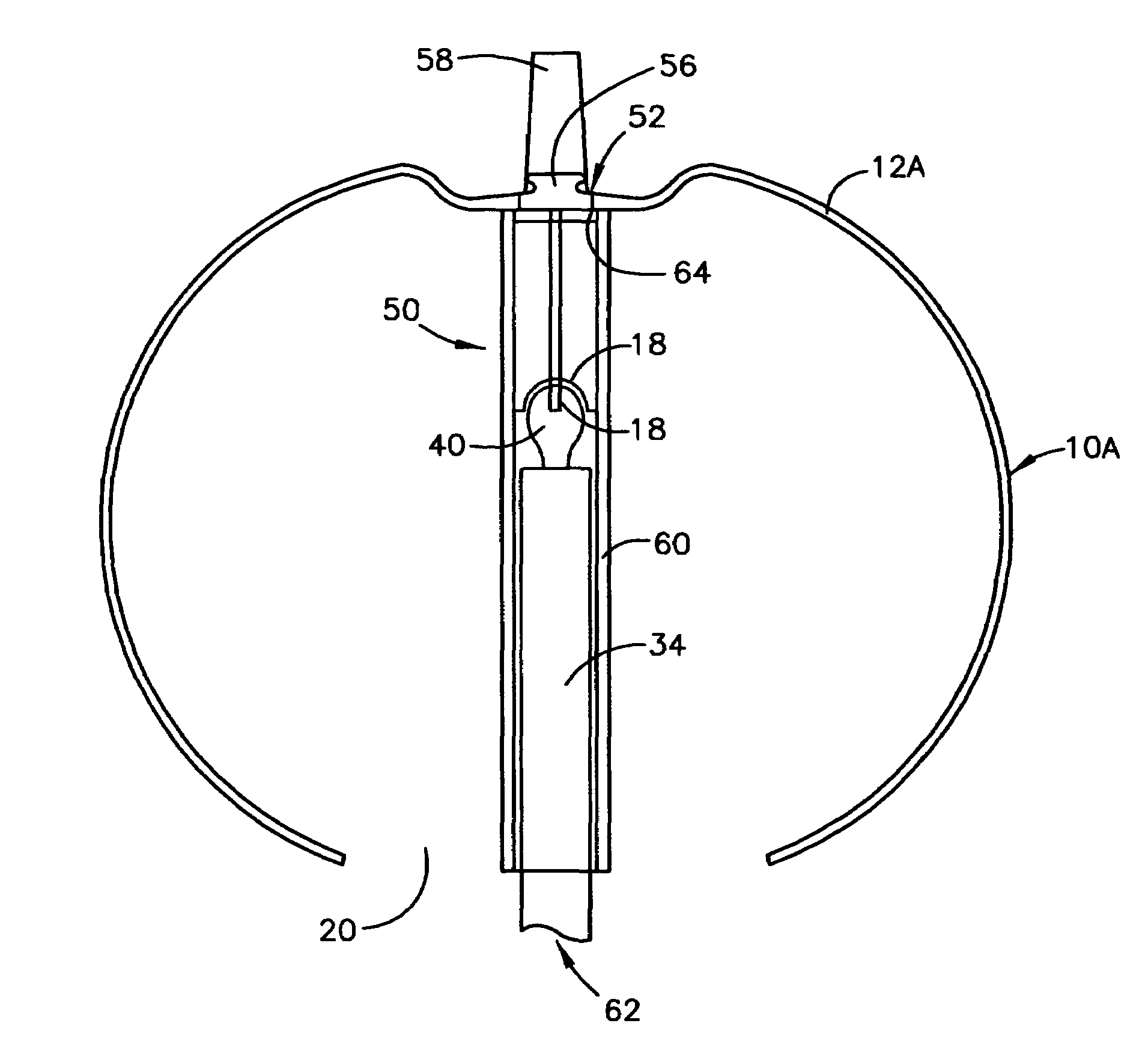
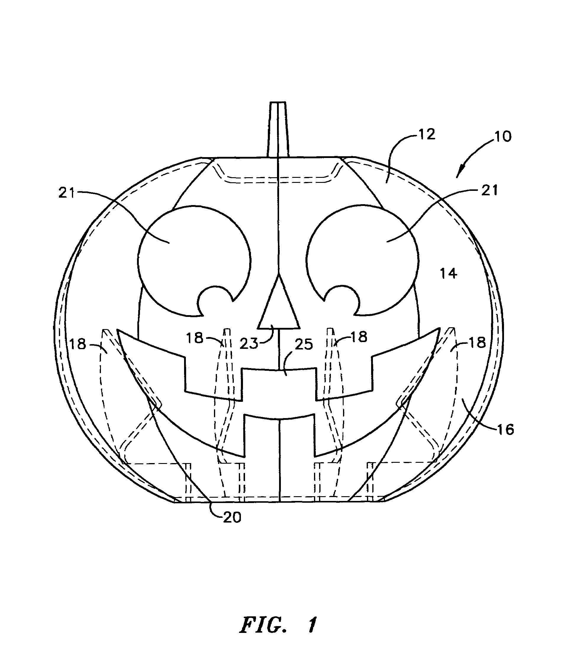
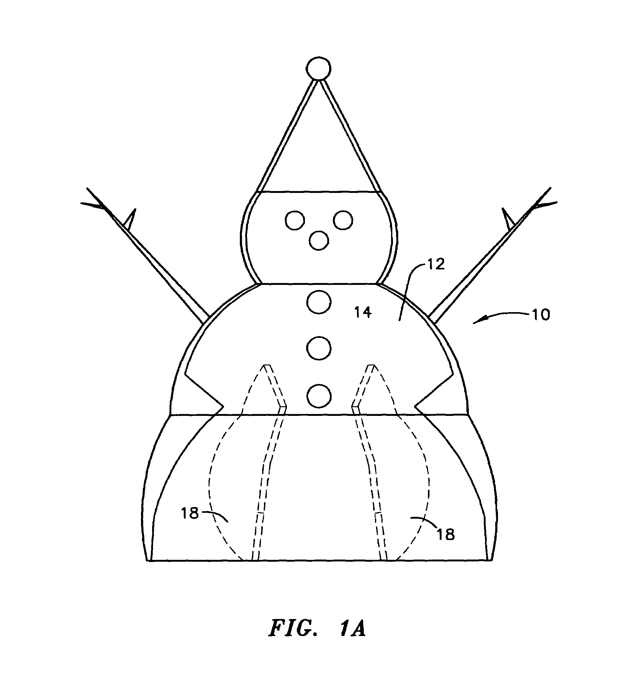
[0027]Referring now to FIGS. 1, 1A and 2, the lamp cover 10 of the present invention comprises a hollow pliant shell 12 having an exterior surface 14 the provide some type of decorative shape, in the case of FIG. 1 a “pumpkin” or “jack-o-lantern” of the type used in Halloween decorations and in the case of FIG. 1A a snowman of the type that would be used for a Christmas or winter decoration. As will be described in greater detail hereinafter, lamp cover 10 is preferably at least partially translucent and partially opaque to permit proper display of the exterior decorative shape and details thereof when applied to a lighting fixture as described below. According to the embodiment depicted in FIGS. 1, 2 and 4–7 lamp cover 10 also has an interior surface 16 from which extend inwardly a plurality of pliant ribs 18 whose purpose, as described below, is to engage a light bulb, lens, globe or lighting fixture to which lamp cover 10 is applied through insertion of the light bulb or lighting...


PUM


Abstract

A lamp cover or shade comprising a hollow pliant shell having an exterior surface in the form of a decorative shape and an interior surface having pliant ribs extending inwardly from the interior surface, or an integral interior cylinder which ribs or cylinder are of a size and shape as to frictionally or elastically engage the exterior of a light fixture lens, bulb cover or bulb. According to a preferred embodiment, the lamp cover is fabricated from an elastic, pliable and high temperature resistant polymeric material that permits its close contact with a low voltage or conventional light bulbs.

Description

[0001]This application is a continuation-in-part of U.S. patent application Ser. No. 10 / 274,592 filed, Oct. 21, 2002 now U.S. Pat. No. 6,746,136 and Ser. No. 10 / 418,331 filed Apr. 18, 2003 now U.S. Pat. No. 6,902,297 and herewith.FIELD OF THE INVENTION[0002]The present invention relates to lamp shades or covers and more particularly to such devices for primarily exterior lighting applications that are durable, readily interchangeable and fashionably decorative.BACKGROUND OF THE INVENTION[0003]Decorative exterior lighting, for example along walkways, driveways and in garden areas, has become very popular. Such lighting can be low voltage, i.e. 12 / 24 volts driven by a transformer or solar powered, or 110 volts (in the U.S.). Low voltage lighting produces relatively small amounts of heat and thus is low temperature, while the more conventional incandescent lighting produces significant heat and higher temperatures, on the order of several hundred degrees Fahrenheit. The latter situatio...

Claims


Application Information

Patent Timeline
IPC IPC(8): F21V1/00
CPCF21V1/16F21V21/0824F21V17/04F21W2121/00
Inventor FUNG, DUNCAN C.
Owner FUNG DUNCAN C
Why Eureka
Try Eureka