Sheet metal bending brake with improved hinge

a technology of hinge mechanism and bending brake, which is applied in the field of sheet metal bending brake with an improved hinge, can solve the problems of many of the previously known hinge mechanism of sheet metal bending brake, all of these previously known pivoting mechanisms, and all suffer from one or more common problems,

Inactive Publication Date: 2007-03-20
TAPCO INTERNATIONAL CORPORATON
View PDF14 Cites 15 Cited by
  • Summary
  • Abstract
  • Description
  • Claims
  • Application Information

AI Technical Summary

Problems solved by technology

All of these previously known pivoting mechanisms, however, all suffer from one or more common problems.
In many situations, such scuffing is cosmetically unacceptable.
Similarly, many of the previously known hinge mechanisms for sheet metal bending brakes are incapable of bending the sheet metal when only a very small amount of sheet metal protrudes outwardly from the clamping jaw.
For example, many previously known bending brakes are incapable of forming a bend in sheet metal of less than 3 / 16 of an inch in width.
Similarly, many of the previously known hinge mechanisms for sheet metal bending brakes are incapable of producing hems of very small widths.

Method used


Image

  • Sheet metal bending brake with improved hinge
  • Sheet metal bending brake with improved hinge
  • Sheet metal bending brake with improved hinge

Examples


Embodiment Construction

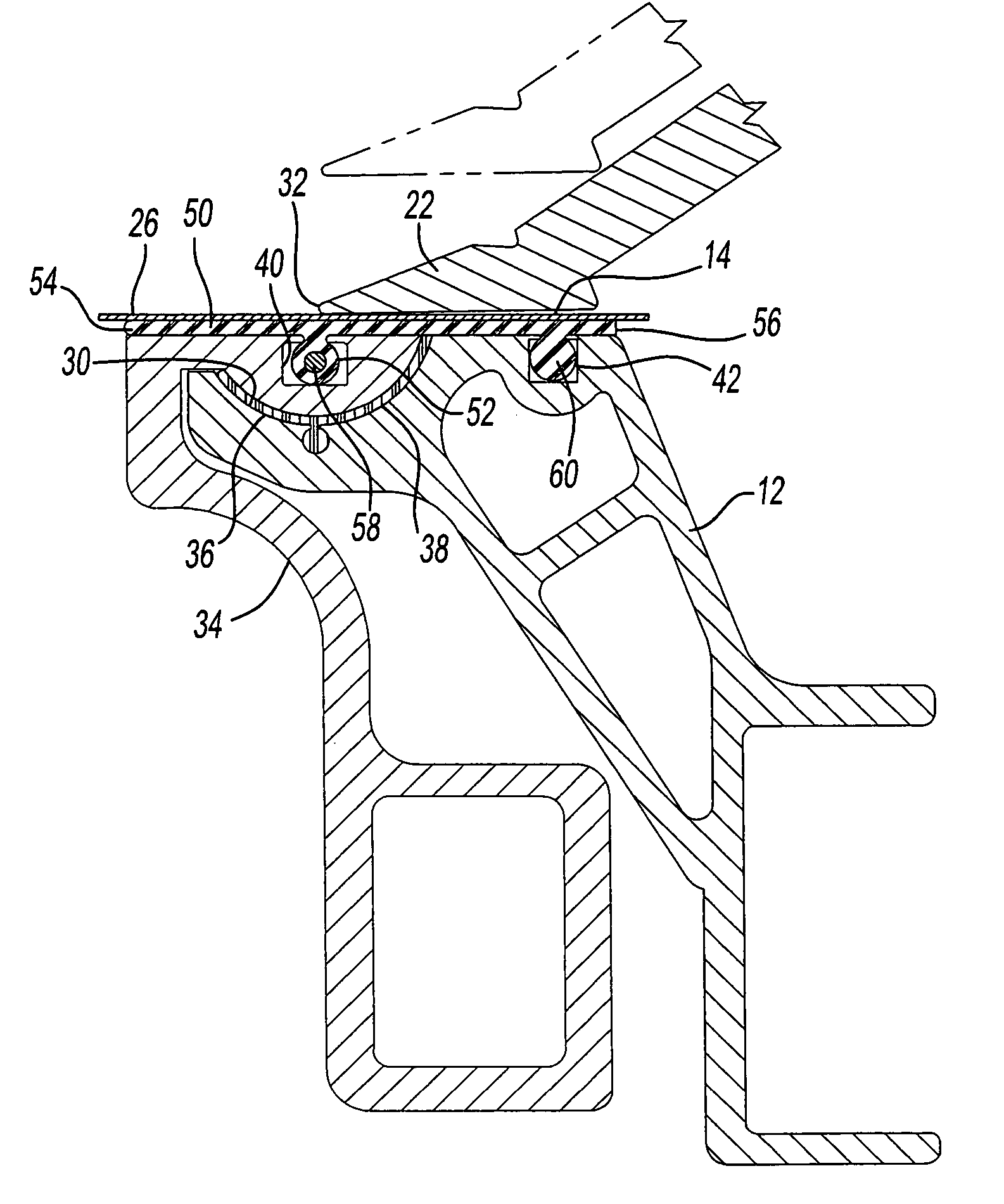
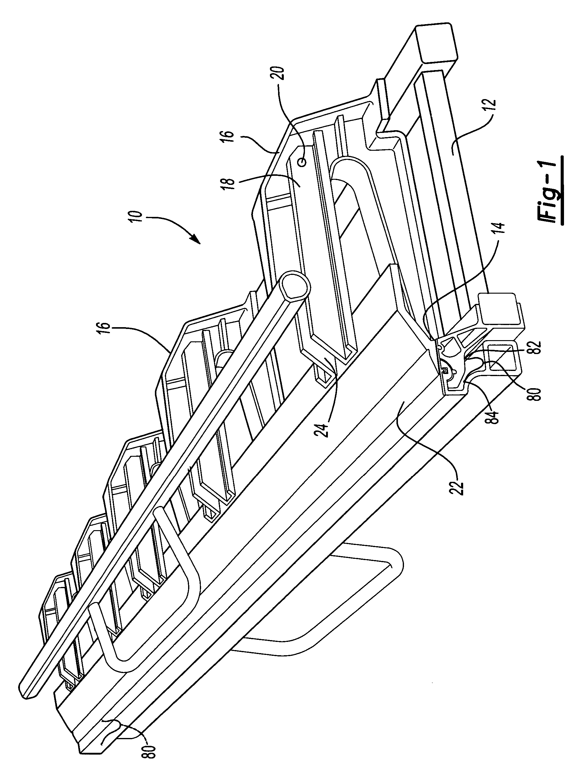
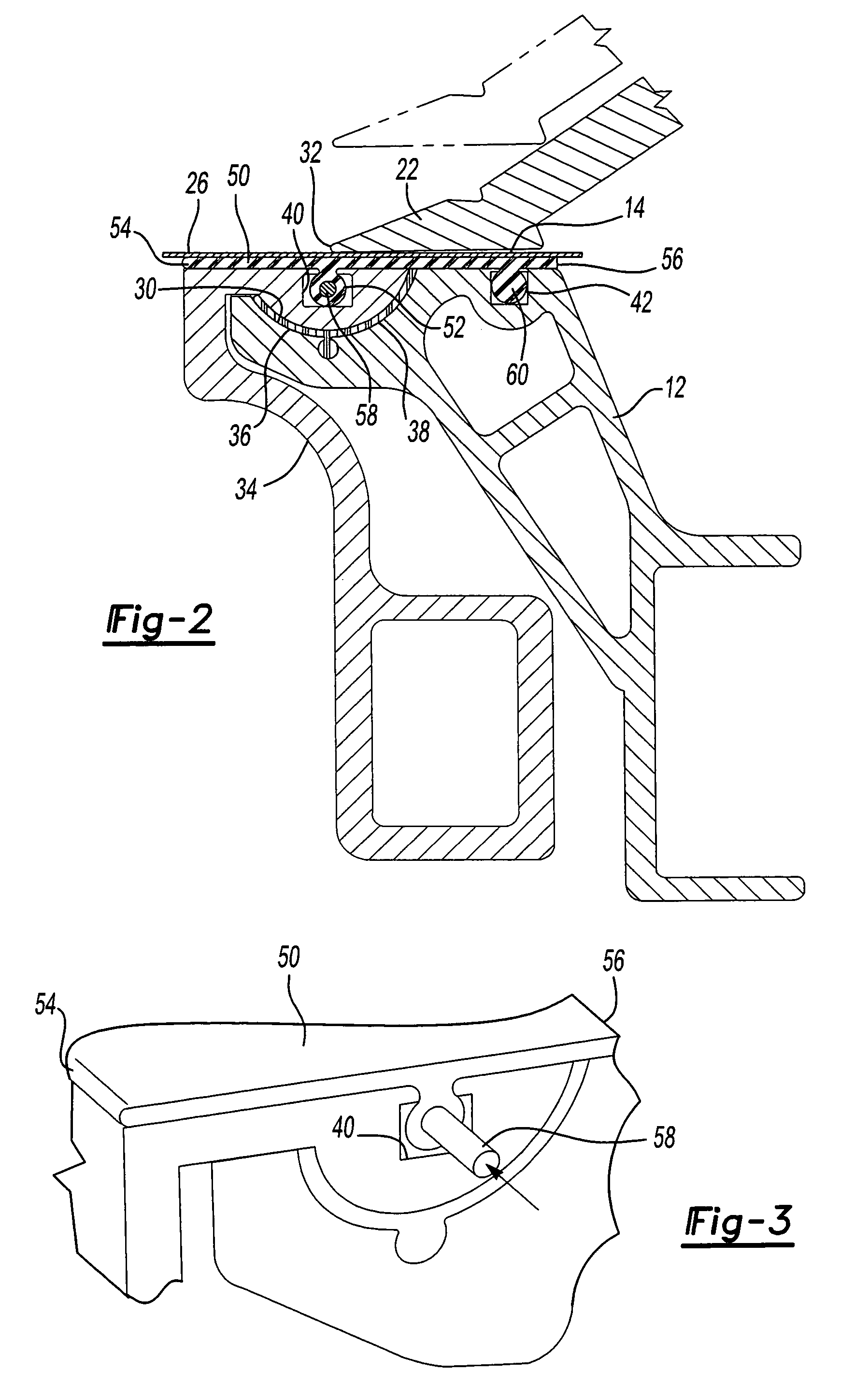
[0022]With reference first to FIG. 1, a preferred embodiment of the portable sheet metal bending brake 10 of the present invention is shown and includes a stationary frame 12 which is constructed of any rigid material, such as metal. The frame 12 is supported in any conventional fashion, such as by a stand (not shown). Additionally, the frame 12 includes an elongated sheet metal support surface 14 which is adapted to receive and support a piece of sheet metal within the bending brake 10.

[0023]A plurality of rigid frame members 16 are secured to the frame 12 such that the frame members 16 are longitudinally spaced from each other along the frame 12. The frame members 16 are secured to the frame 12 such that the frame members 16 are spaced upwardly from the sheet metal support surface 14.

[0024]A pivot arm 18 is pivotally secured at one end 20 to each frame member 16 so that the pivot arms 18 are also longitudinally spaced apart from each other along the frame 12. An elongated clamping...


PUM

PropertyMeasurementUnit
flexibleaaaaaaaaaa
cross-sectional shapeaaaaaaaaaa
molecular weightaaaaaaaaaa

Abstract

A sheet metal bending brake having a frame with a sheet metal support surface. A clamping jaw is movable relative to the frame support surface to clamp the sheet metal between the clamping jaw and the frame. The clamping jaw has a linear front edge. An elongated bending arm is pivotally mounted to the frame by an elongated flexible strap having spaced apart edges. One edge of the strap is secured to the bending arm while the other edge of the strap is secured to the frame such that the bending arm extends parallel to and closely adjacent the clamping jaw front edge.

Description

RELATED APPLICATIONS[0001]This application claims priority of U.S. Provisional Patent Applications Ser. No. 60 / 520,472 filed Nov. 14, 2003 and Ser. No. 60 / 532,281 filed Dec. 23, 2003, which are incorporated herein by reference.BACKGROUND OF THE INVENTION[0002]I. Field of the Invention[0003]The present invention relates generally to sheet metal bending brakes and, more particularly, to a sheet metal bending brake with an improved hinge.[0004]II. Description of Related Art[0005]There are many previously known portable sheet metal bending brakes that are used in the building industry, typically for the installation of aluminum siding. These previously known sheet metal bending brakes typically comprise a frame having a planar work support surface which supports the sheet metal as well as a plurality of spaced frame members which extend over the work support surface.[0006]A plurality of elongated pivot arms are pivotally secured at one end to the spaced apart frame members. An elongated...

Claims


Application Information

Patent Timeline
Patent Type & Authority Patents(United States)
IPC IPC(8): B21D5/04
CPCB21D5/04B21D5/042
Inventor BREAK, DOUGLAS
Owner TAPCO INTERNATIONAL CORPORATON
Why Eureka
Try Eureka