Developing apparatus and image forming apparatus that incorporates the developing apparatus

a technology of developing apparatus and developing apparatus, applied in the direction of electrographic process apparatus, shaft and bearing, instruments, etc., can solve the problem of still leakage of toner and achieve the effect of preventing toner

Active Publication Date: 2007-03-27
OKI ELECTRIC IND CO LTD
View PDF8 Cites 11 Cited by
  • Summary
  • Abstract
  • Description
  • Claims
  • Application Information

AI Technical Summary

Benefits of technology

[0006]An object of the invention is to prevent toner from leaking from a developing unit.
[0008]Still another object of the invention is to provide a configuration of a developing apparatus in which the toner is pushed back toward the middle portion of the developing roller, thereby preventing toner leakage.
[0009]Yet another object of the invention is to provide a configuration of a developing apparatus in which a sealing member is pressed against the surface of the end portion of the resilient layer of the developing roller, thereby preventing toner leakage.

Problems solved by technology

However, the sealing members 9 pressed against the longitudinal end portions of the developing roller 4 are not sufficient and some toner still leaks.

Method used


Image

  • Developing apparatus and image forming apparatus that incorporates the developing apparatus
  • Developing apparatus and image forming apparatus that incorporates the developing apparatus
  • Developing apparatus and image forming apparatus that incorporates the developing apparatus

Examples


first embodiment

{Construction}

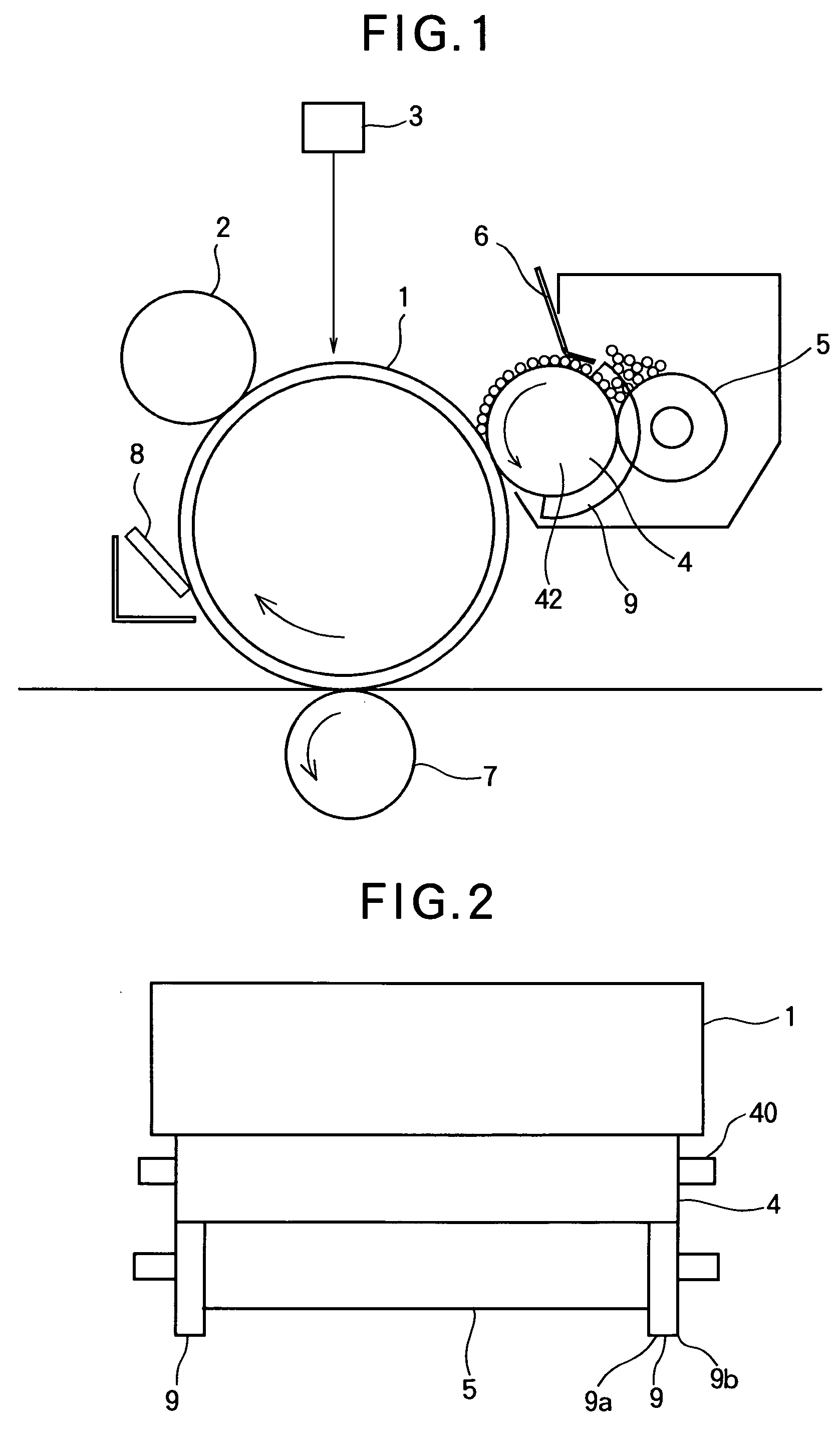
[0039]FIG. 1 is an electrophotographic image forming apparatus according to a first embodiment.

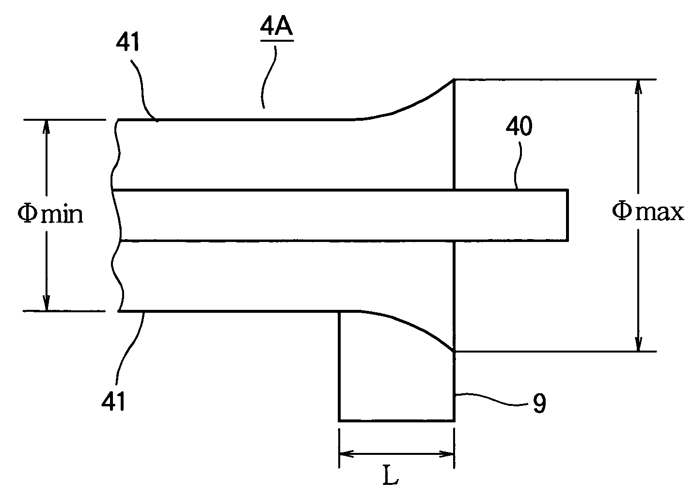
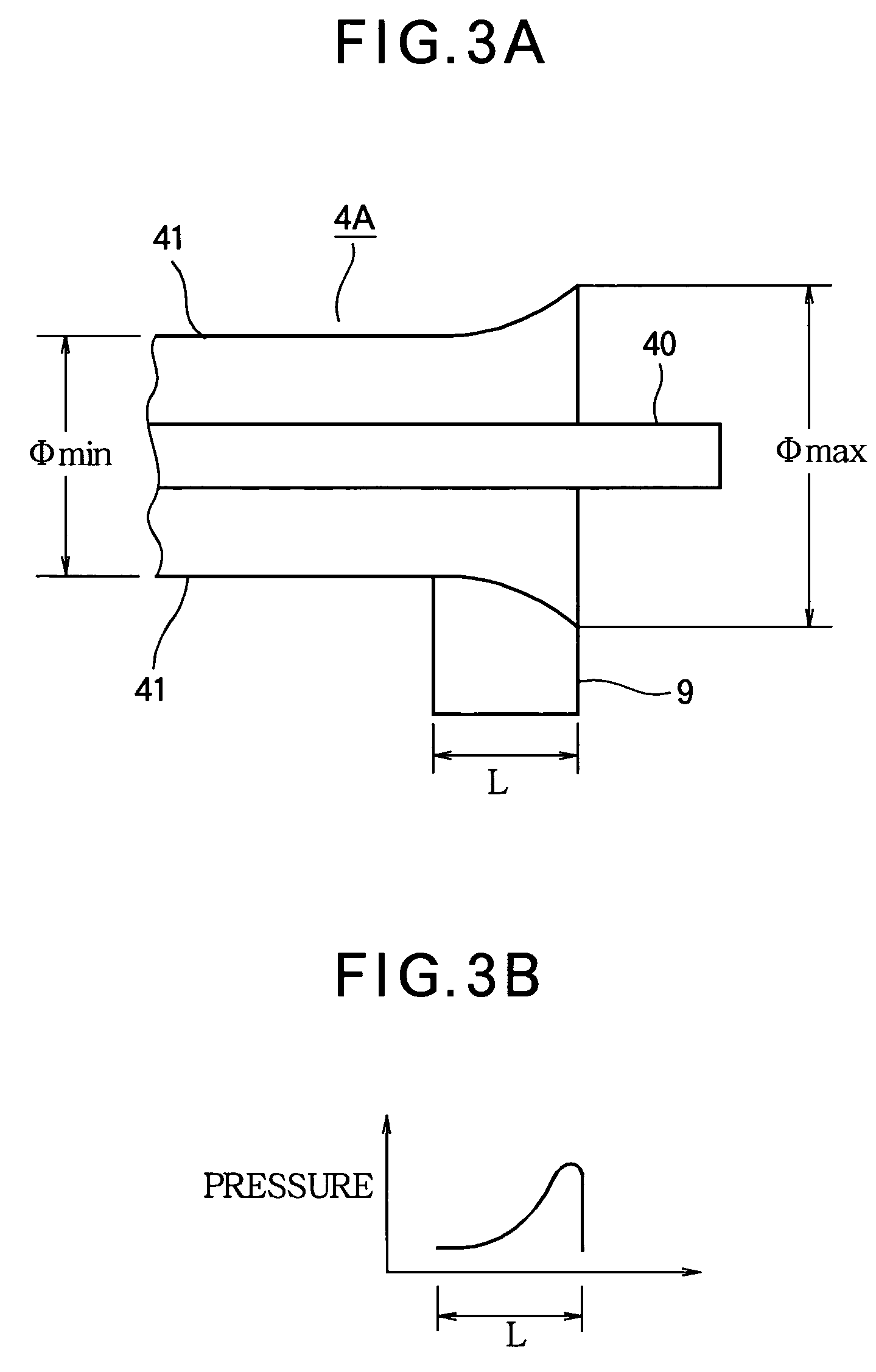
[0040]Referring to FIG. 1, a photoconductive drum 1, a charging roller 2, a light source 3, a developing roller 4, a toner-supplying roller 5, transfer roller 7 that extend longitudinally and rotate. The cleaning blade 8, a developing 6, and a sealing member 9 extend in their longitudinal directions. The charging roller 2, developing roller 4, transfer roller 7, cleaning blade 8 are in contact with the photoconductive drum 1. The developing blade 8 and toner-supplying roller 5 are adjacent to and parallel to the developing roller 4. The sealing member 9 is disposed in the vicinity of the longitudinal ends of the developing roller 4, being pressed against the circumferential surface of the developing roller 4.

[0041]FIG. 2 illustrates the positional relation among the photoconductive drum 1, developing roller 4, toner-supplying roller 5, and sealing member 9. The sealing member...

second embodiment

[0050]An electrophotographic image forming apparatus according to a second embodiment has the same configuration as the first embodiment. FIG. 7 is a cross-sectional view of a developing roller 4D. The developing roller 4D is provided with a resilient layer 43 that covers the outer circumference of a meal shaft 40. The resilient layer 43 is formed of a semiconductive material such as silicone rubber or urethane. The developing roller 4D is polished at an area in contact with a sealing member 9 in such a way that the diameter becomes larger nearer the longitudinal ends. It is to be noted that the diameter does not change linearly but exponentially. In other words, the developing roller 4D is shaped such that the diameter of the resilient layer 43 becomes larger nearer the longitudinal ends. The resilient layer 43 may be of dual-layer structure as in the first embodiment, in which case, a resin coating 42 formed of, e.g., urethane resin, is formed as a second layer on the resilient la...

third embodiment

[0054]An electrophotographic image forming apparatus according to a third embodiment is of the same configuration as the first embodiment. FIG. 8A is a perspective view illustrating the overall shape of a developing roller 4E. FIG. 8B is a front view of the developing roller 4E. The developing roller 4E has a metal shaft 40 covered with a resilient layer 44. The resilient layer 44 may be of dual-layer structure. The developing roller 4E is formed such that the diameter is a maximum (Φmid) at the longitudinally middle portion and becomes continuously progressively smaller nearer the longitudinal end portions to reach a minimum (ΦA) nearer the ends, and then again becomes larger nearer the longitudinal ends, reaching Φend at the longitudinal ends. A sealing member 9 is in contact with the outer surface of the developing roller 4E that extends from ΦA to Φend. The diameters Φend and Φmid are related such that Φend<Φmid. The diameters Φmid and ΦA are related such that 10 μm<(Φmid−ΦA)<20...


PUM


Abstract

A developing apparatus includes a developing roller and a sealing member. The developing roller applies toner to an electrostatic latent image to develop the electrostatic latent image. The sealing member presses the developing roller to seal the developer. The apparatus includes a developing roller with a shaft and a resilient layer formed on the shaft. The developing roller rotates about the shaft. The resilient layer covers the outer circumferential surface of the developing roller and is in contact with the sealing member. The resilient layer has a diameter that becomes larger nearer longitudinal ends of the developing roller. The diameter has a maximum value and a minimum value. The difference between the maximum value and the minimum value is such that 10 μm<ΔΦ<300 μm, where ΔΦ is a difference between the maximum value and the minimum value.

Description

BACKGROUND OF THE INVENTION[0001]1. Field of the Invention[0002]The present invention generally relates to an electrophotographic image-forming apparatus such as a printer and a facsimile machine.[0003]2. Description of the Related Art[0004]A conventional electrophotographic image-forming apparatus is of the configuration as shown in FIG. 1. A charging roller 2 charges the surface of a photoconductive drum 1. A light source 3 illuminates the charged surface of the photoconductive drum 1 in accordance with print data to form an electrostatic latent image. A developing roller 4 applies, for example, toner to the electrostatic latent image to develop the electrostatic latent image into a visible image. A toner-supplying roller 5 charges the toner and supplies the charged toner to the developing roller. A developing blade 6 forms a toner layer having a uniform thickness on the developing roller 4. A transfer roller 7 transfers the toner image from the photoconductive drum 1 onto a recor...

Claims


Application Information

Patent Timeline
Patent Type & Authority Patents(United States)
IPC IPC(8): G03G15/08F16C13/00
CPCG03G15/0817
Inventor OHSHIKA, HIROTAKA
Owner OKI ELECTRIC IND CO LTD
Why Eureka
Try Eureka