Developing device and image forming apparatus

a technology of developing device and developing roller, which is applied in the direction of electrographic process apparatus, instruments, optics, etc., can solve the problems of increasing the load torque of the motor driving the developing roller, and the circumferential surface of the sealing member and the circumferential surface of the developing roller, so as to reduce the size and the manufacturing cost of the image forming apparatus, and prevent the leakage of toner.

Active Publication Date: 2007-04-17
OKI ELECTRIC IND CO LTD
View PDF8 Cites 8 Cited by
  • Summary
  • Abstract
  • Description
  • Claims
  • Application Information

AI Technical Summary

Benefits of technology

[0007]An object of the present invention is to provide a developing device and an image forming apparatus capable of preventing the leakage of a toner outward in the axial direction of the developing roller without increasing a torque for rotating the developing roller.
[0009]With such an arrangement, it becomes possible to obtain a developing device capable of preventing the leakage of the toner outward in the axial direction of the developing roller without increasing the torque for rotating the developing roller. Further, by using the developing device, it becomes possible to reduce the size and the manufacturing cost of the image forming apparatus.

Problems solved by technology

However, in such a case, the friction between the seal members and the circumferential surface of the developing roller may increase, and therefore a load torque of a motor for driving the developing roller may also increase.
As a result, the motor may become larger, and the abrasive wear may increase.

Method used


Image

  • Developing device and image forming apparatus
  • Developing device and image forming apparatus
  • Developing device and image forming apparatus

Examples


embodiment 1

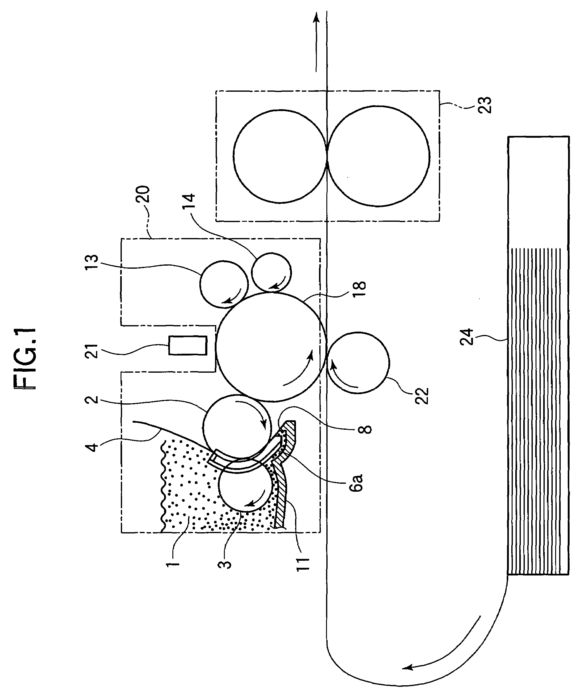
[0025]FIG. 1 is a side view showing a configuration of an image forming apparatus according to Embodiment 1 of the present invention. As shown in FIG. 1, the image forming apparatus includes an image forming cartridge 20 detachably attached to a main body of the image forming apparatus, an exposing device 21, a transferring device 22, a fixing device 23 and a medium feeding device 24.

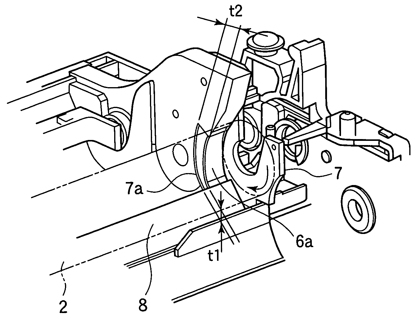
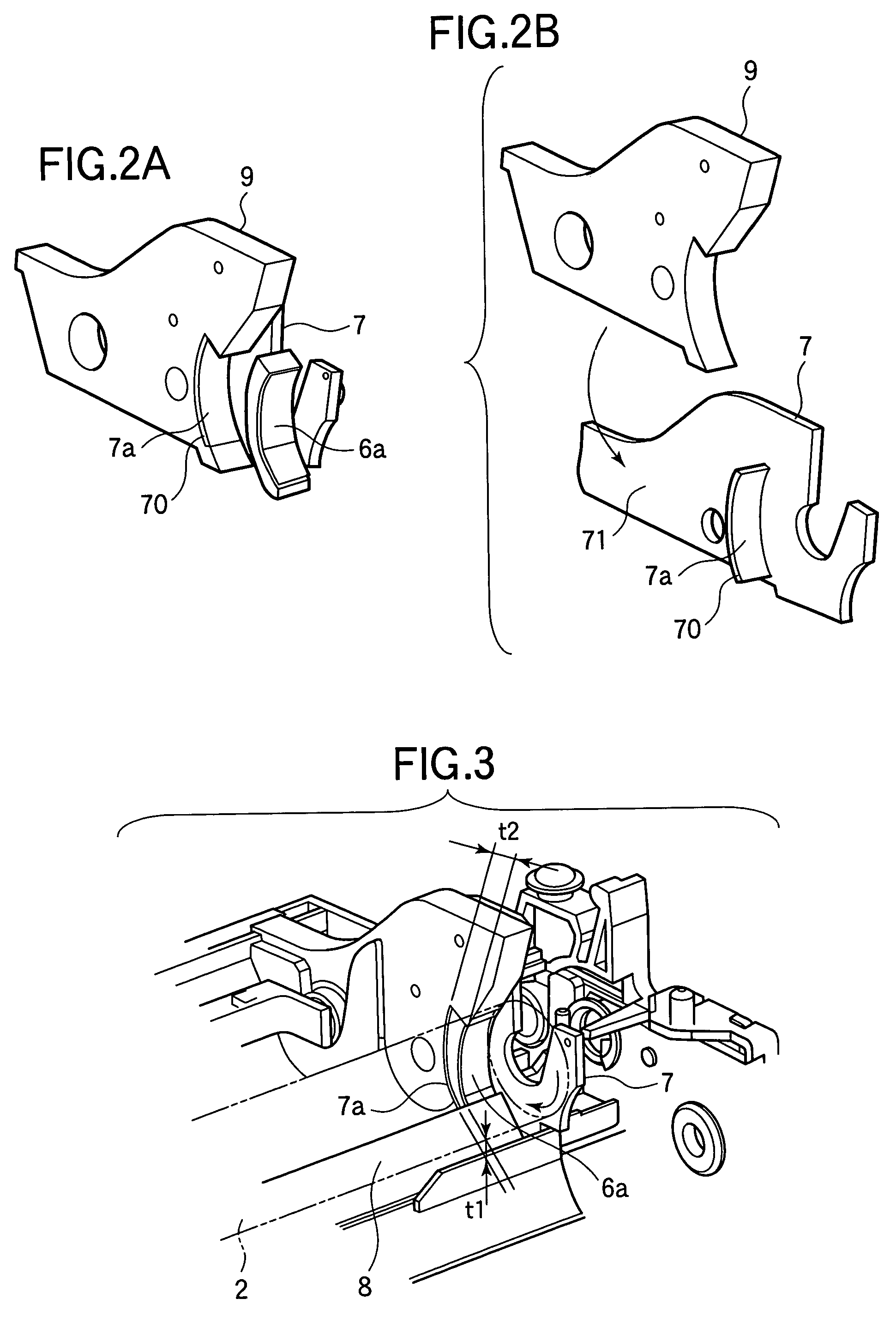
[0026]The image forming cartridge 20 includes a toner storing portion 1 in which a toner (i.e., a developer) is stored, a developing roller 2 having a conductive metal shaft on which a semiconductive rubber (such as silicone rubber) is formed, and a supply roller 3 made of a sponge-like rubber (to which a foaming agent has been added in a kneading process for enhancing the ability to carry the toner) formed into the shape of a roller. The image forming cartridge 20 further includes a developing blade 4 that uniformly regulates the thickness of a toner layer formed on the developing roller 2, seal member...

embodiment 2

[0042]FIG. 6 is a perspective view of a seal member 6b mounted in an image forming apparatus according to Embodiment 2. FIG. 7 is a side view showing the seal member 6b and the developing member 2. In Embodiment 2, the seal member 6b is used instead of the seal member 6a (FIG. 2) of Embodiment 1. Other components of Embodiment 2 are the same as those of Embodiment 1. The thickness of the seal member 6b does not change along the rotational direction of the developing roller 2. In other words, the thickness t1 and t2 of the upstream and downstream ends of the seal member 6a are substantially the same.

[0043]However, as shown in FIG. 7, a bonding surface 7b of the side plate 7 (for bonding the seal member 6b) is so shaped that the distance between the bonding surface 7b and the rotation axis of the developing roller 2 continuously decreases along the rotational direction of the developing roller 2 from the upstream to the downstream. Thus, in a state where the seal member 6b is not comp...

embodiment 3

[0046]FIG. 8A is a perspective view of a seal member 6c mounted in an image forming apparatus according to Embodiment 3. In Embodiment 3, the seal member 6c is used instead of the seal member 6a (FIG. 2) of Embodiment 1. Other components of Embodiment 3 are the same as those of Embodiment 1. As was described in Embodiment 1, the thickness of the seal member 6c continuously increases from t1 to t2 (t2>t1) along the rotational direction of the developing roller 2 from the upstream to the downstream, so that the compressed amount of the compressed portion of the seal member 6c increases along the rotational direction of the developing roller 2 from the upstream to the downstream. The pressure P1 at the upstream end of the seal member 6c is preferably from 0 to 15 kgf / cm2 (i.e., from 0 to 1.47 MPa), and the pressure P2 at the downstream end of the seal member 6c is preferably from 25 to 80 kgf / cm2 (i.e., from 2.45 to 7.84 MPa).

[0047]In Embodiment 3, fibers 10 are bonded to the surface o...


PUM


Abstract

A developing device includes a photosensitive body (18) on which a latent image formed, and a developing roller (2) that rotates to supply a toner to the photosensitive body (18). Seal members (6a) are provided on both end portions of the developing roller (2). The thickness of each seal member (6a) increases along the rotational direction of the developing roller (2) from the upstream to the downstream, so that the pressure with which the seal member (6a) is pressed against the developing roller (2) increases along the rotational direction of the developing roller (2) from the upstream to the downstream.

Description

BACKGROUND OF THE INVENTION[0001]This invention relates to an image forming apparatus such as an electrophotographic apparatus, and particularly to a technology for preventing the leakage of a toner from a developing device of the image forming apparatus.[0002]Generally, a developing device used in an image forming apparatus (for example, an electrophotographic apparatus) includes a developing roller that supplies a toner to a photosensitive drum, and a supply roller that supplies the toner stored in a toner storing portion to the developing roller. In order to prevent the toner moving outward in the axial direction of the developing roller from leaking out of the developing device, seal members are fixed to a casing of the developing device. The seal members slidably contact a circumferential surface of both ends of the developing roller. If the contact area between the seal members and the circumferential surface of the developing roller is increased, the effect of preventing the ...

Claims


Application Information

Patent Timeline
Patent Type & Authority Patents(United States)
IPC IPC(8): G03G15/08
CPCG03G15/0898
Inventor NOZAWA, KEN
Owner OKI ELECTRIC IND CO LTD
Why Eureka
Try Eureka