Liquid spray gun with non-circular horn air outlet passageways and apertures

a non-circular, air outlet technology, applied in the direction of burners, combustion types, combustion processes, etc., can solve the problems of unsatisfactory uniformity, uniform width of the stream, and inability to achieve the effect of uniformity

Active Publication Date: 2007-04-10
3M INNOVATIVE PROPERTIES CO
View PDF28 Cites 106 Cited by
  • Summary
  • Abstract
  • Description
  • Claims
  • Application Information

AI Technical Summary

Benefits of technology

[0004]The present invention provides a liquid spray gun that can provide an improved shape and distribution of liquid flow within the wide elongate stream of liquid formed by the spray gun.
[0008]The nozzle portion as well as the air cap portion can be molded of polymeric material, and the liquid spray gun can further include a reusable platform portion (e.g., of metal) having through air distribution passageways including an inlet opening adapted to be connected to a supply of air under greater than atmospheric pressure, first and second air outlet openings, means for separately regulating the flow of air through the first and second air outlet openings of the air distribution passageways when air is flowing through the air distribution passageways, and manually operated means for stopping or allowing flow of air through the outlet openings of the air distribution passageways. The reusable platform portion and the polymeric nozzle portion can then have manually operable means (i.e., means manually operable by a person without the use of tools) for releasably mounting the nozzle portion on the reusable platform portion with the first and second air outlet openings of the air distribution passageways communicating with inlet ends of the first and second passageways. The molded air cap and nozzle portions can be sufficiently inexpensive that they can be discarded rather than cleaned for some applications

Problems solved by technology

While such cylindrical air streams from cylindrical passageways placed on the horns can form a wide elongate stream of liquid, the uniformity of the width of that stream and the uniformity in the amount of liquid delivered per unit time along its length are not as good as may be desired because such cylindrical air streams do not apply a uniform amount of energy across their diameters against the side of the stream of liquid.

Method used


Image

  • Liquid spray gun with non-circular horn air outlet passageways and apertures
  • Liquid spray gun with non-circular horn air outlet passageways and apertures
  • Liquid spray gun with non-circular horn air outlet passageways and apertures

Examples


Embodiment Construction

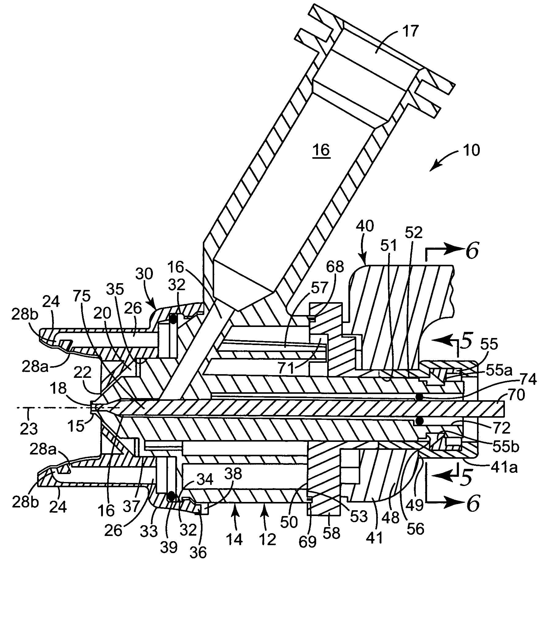
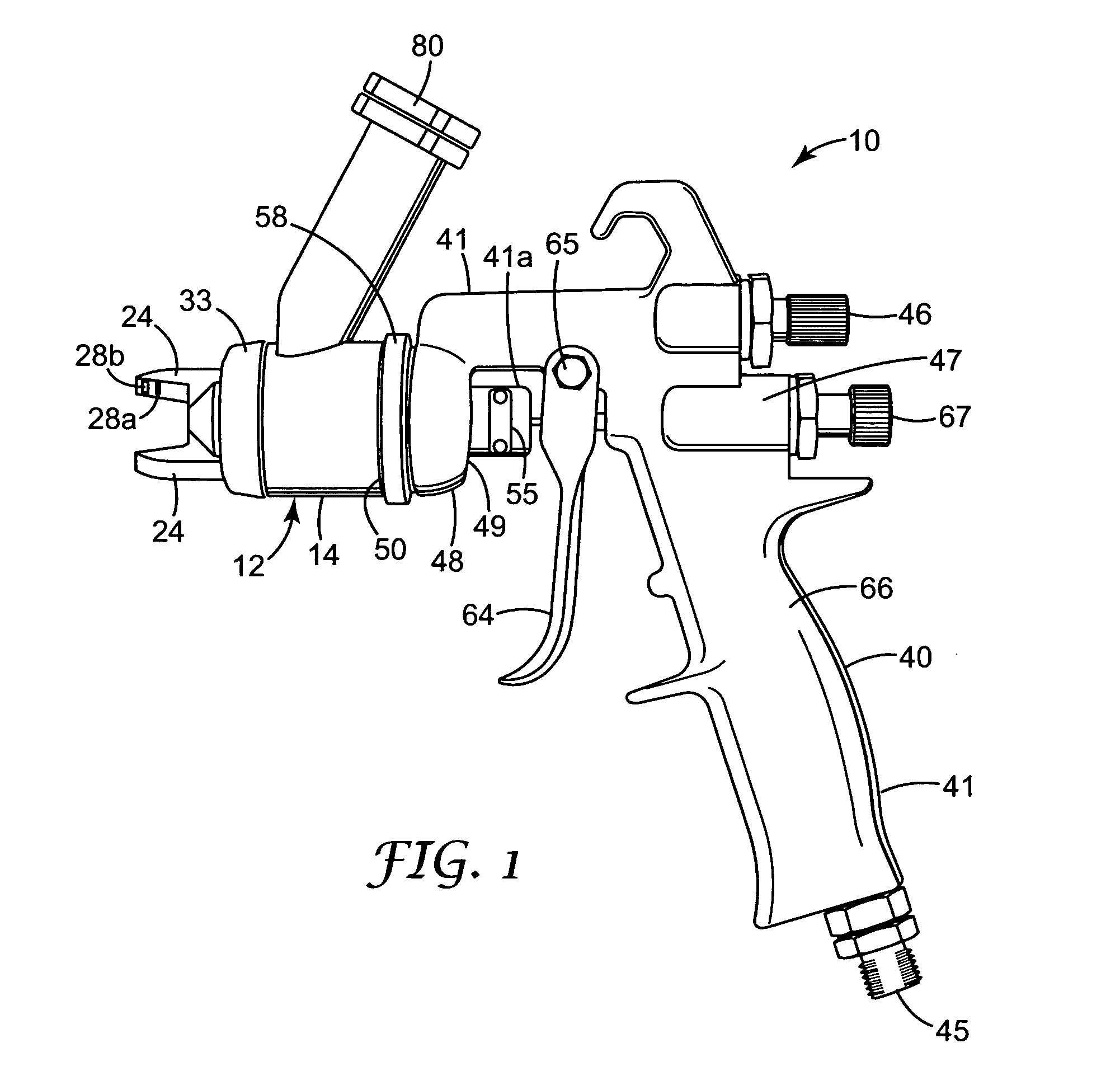
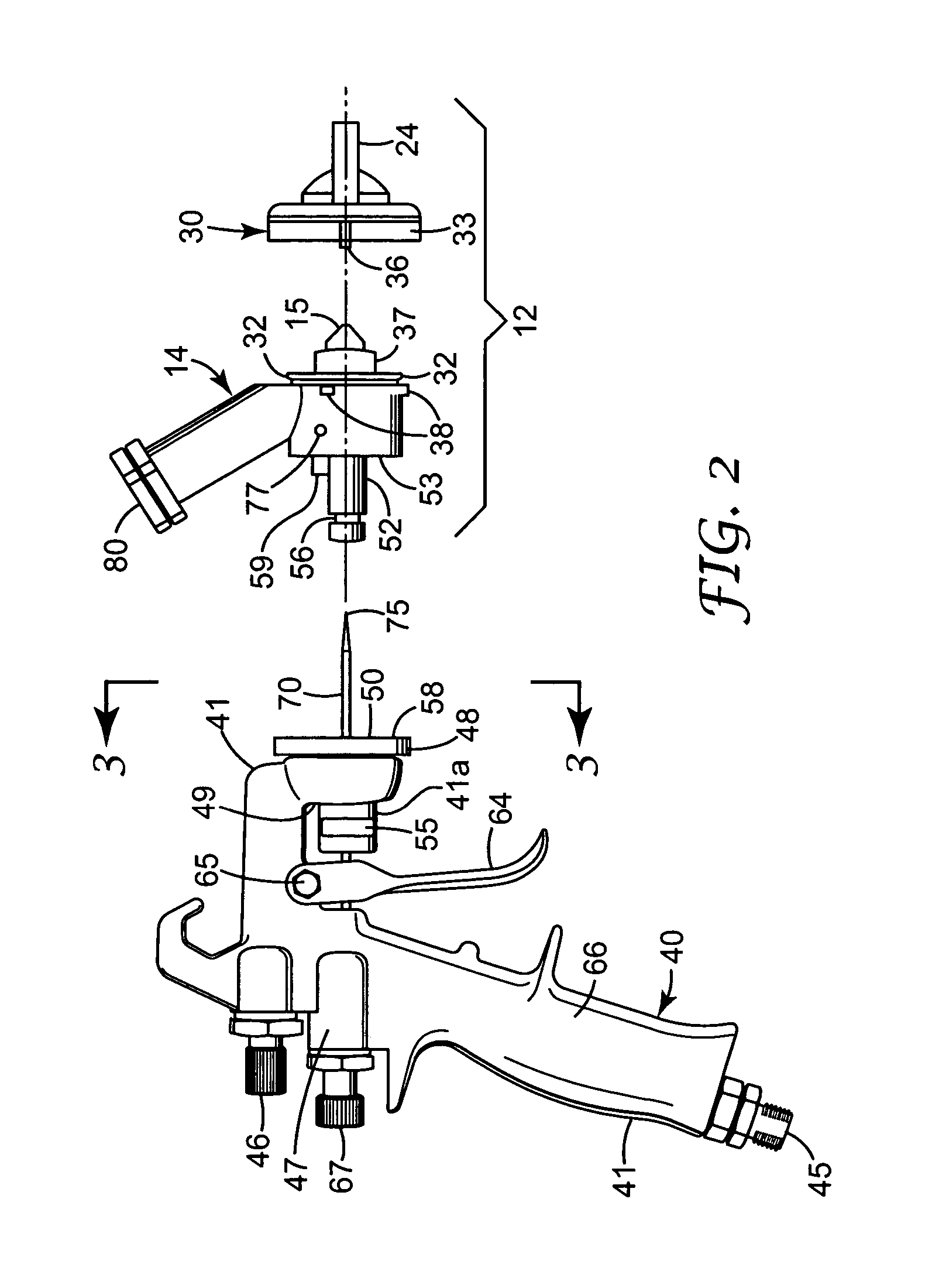
[0024]Referring now to the drawing there is illustrated a liquid spraying device or spray gun 10 according to the present invention. Generally, the liquid spray gun 10 comprises a body assembly 12 including a nozzle portion 14 with an outlet end 15. The nozzle portion 14 has a liquid passageway 16 extending from an inlet end 17 to an outlet end 18 opening through the outlet end 15 of the nozzle portion 14. The body assembly 12 also has a first air passageway 20 extending from an inlet end 21 to an outlet end 22 at the outlet end 15 of the nozzle portion 14. The outlet end 22 of the first air passageway 20 extends around the outlet end 18 of the liquid passageway 16 and is shaped to direct air under greater than atmospheric pressure against liquid flowing out of the outlet end 18 of the liquid passageway 16 to propel liquid flowing out of the liquid passageway 16 away from the outlet end 15 of the nozzle portion 14 while shaping the liquid into a generally conical stream about an axi...


PUM


Abstract

The present invention provides a liquid spray gun with several improved features, including (1) non-cylindrical air passageways on air horns included in an air cap portion of a body assembly that provide improved shape and uniformity for the wide elongate stream of liquid formed by the spray gun; (2) the air cap portion of the body assembly being mounted for manual rotation on a nozzle portion of the body assembly between positions defined by stops and retained at those positions by friction; and (3) the body assembly through which passes liquid sprayed by the spray gun being molded of polymeric material and being manually releasable from a metal platform portion of the spray gun through which air is fed to passageways through the body assembly to spray the liquid.

Description

FIELD OF THE INVENTION[0001]This invention relates to liquid spray guns of the type comprising a body assembly having a liquid passageway with an outlet end opening through an outlet end of a nozzle portion, which body assembly has a first air passageway having an outlet end around the outlet end of the liquid passageway shaped to direct high velocity air against liquid flowing out of the outlet end of the liquid passageway to propel the liquid away from the nozzle portion while shaping the liquid into a generally conical stream about an axis; the body assembly including horns projecting past the outlet end of the nozzle portion on opposite sides of the axis, and having a second air passageway extending to outlet passageways and apertures spaced along the horns from the outlet end of the nozzle portion and facing opposite sides of the axis, which horn outlet passageways and apertures are positioned to direct high velocity air against opposite sides of a stream of liquid formed by ai...

Claims


Application Information

Patent Timeline
Patent Type & Authority Patents(United States)
IPC IPC(8): A62C31/02B05B1/26B05B7/06B05B7/08B05B7/12B05B7/24
CPCB05B7/0815B05B7/083B05B7/1209B05B7/2478B05B7/066
Inventor BLETTE, RUSSELL E.FREDERICKSON, FRANKLYN L.JOSEPH, STEPHEN C. P.QIBLAWI, JAMEEL R.
Owner 3M INNOVATIVE PROPERTIES CO
Why Eureka
Try Eureka