Golf ball dimples

a technology of golf ball and dimple, which is applied in the field of golf balls, can solve the problems of small dimples not always very effective in reducing drag and increasing lift, and the aerodynamic performance of the ball is not improved in space,

Inactive Publication Date: 2007-06-12
ACUSHNET CO
View PDF36 Cites 79 Cited by
  • Summary
  • Abstract
  • Description
  • Claims
  • Application Information

AI Technical Summary

Problems solved by technology

This is the primary source of drag for golf balls.
In arranging the dimples, an attempt is made to minimize the space between dimples, because such space does not improve aerodynamic performance of the ball.
However, in reality small dimples are not always very effective in decreasing drag and increasing lift.
This results at least in part from the susceptibility of small dimples to paint flooding.
Paint flooding occurs when the paint coat on the golf ball partially fills the small dimples, and consequently decreases the dimple's aerodynamic effectiveness.
On the other hand, a smaller number of large dimples also begin to lose effectiveness.
However, it has been demonstrated that polygonal dimples with polyhedron dimple surfaces do not achieve performance improvements commensurate with their coverage improvements.

Method used


Image

  • Golf ball dimples
  • Golf ball dimples
  • Golf ball dimples

Examples


Embodiment Construction

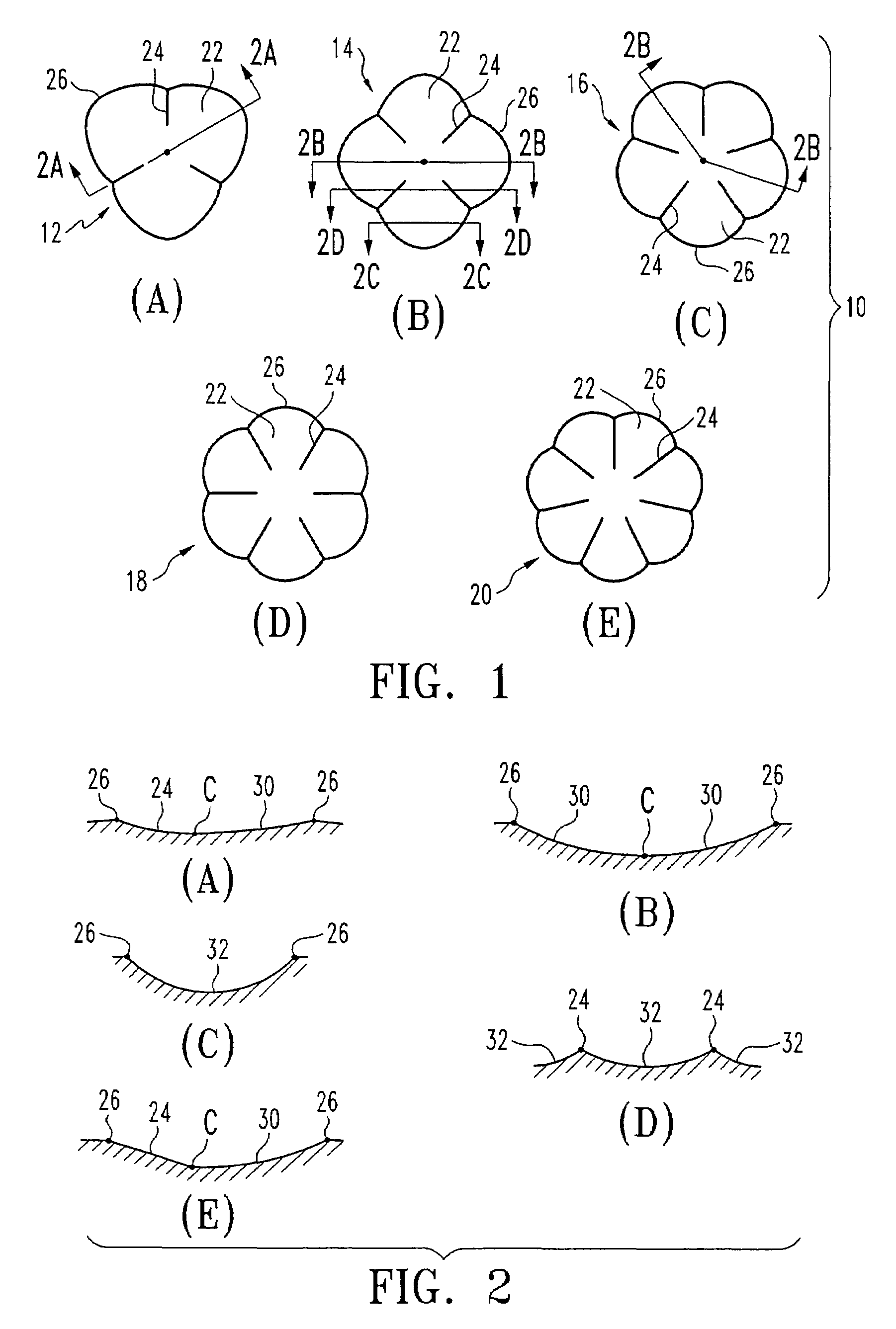
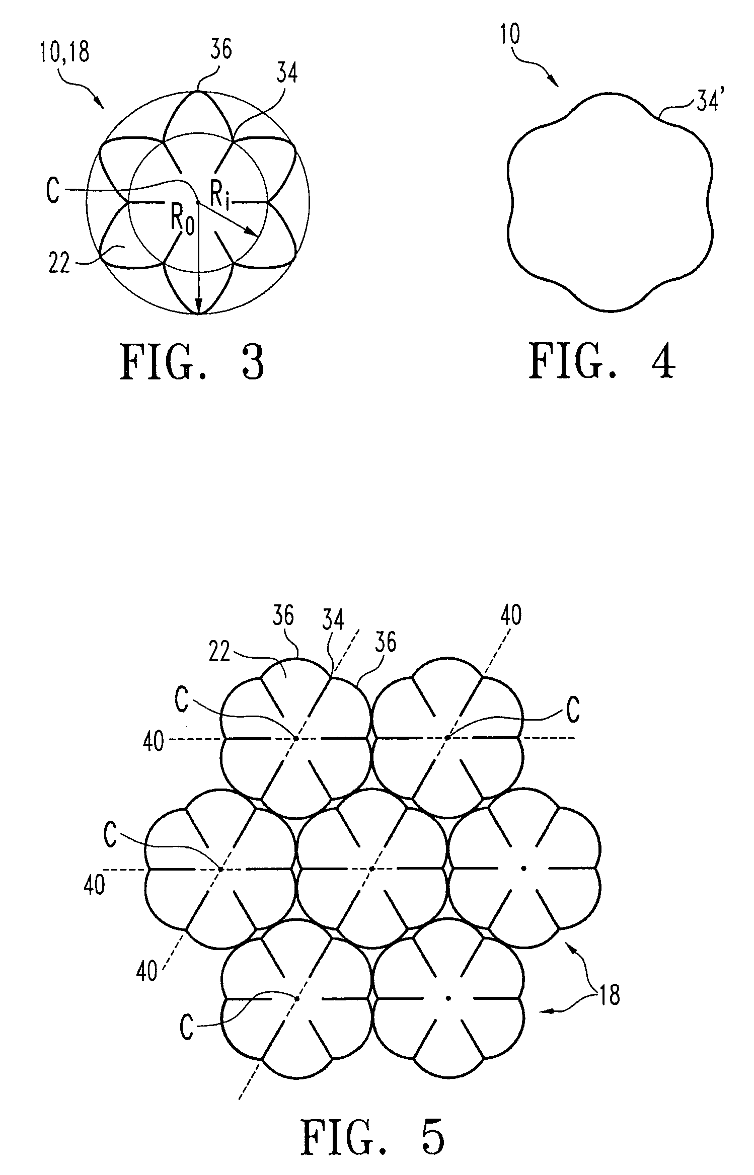
[0029]As illustrated in FIGS. 1(A) to 1(E), where like numbers designate like parts, reference number 10 generally designates the inventive multi-lobed dimple of the present invention and reference numbers 12, 14, 16, 18 and 20 specifically designate some of the preferred embodiments of the multi-lobed dimple 10 in accordance to the present invention. Preferably, the multi-lobed dimple 10, as shown in FIGS. 1–6, comprises uniform lobes, i.e., uniform size, shape and angular spacing.

[0030]In accordance to one aspect of the invention, the dimple 10 comprises a plurality of lobes 22, arranged radially around the center C of the dimple. Each lobe 22 is preferably separated from adjacent lobes by radial lines or spoke-like ridges 24. Preferably, dimple 10 has at least three lobes. FIGS. 1(A)–1(E) illustrate dimple 10 having three lobes to seven lobes, respectively. Dimple 10 may have any number of lobes and the present invention is not limited to any specific embodiment illustrated herei...


PUM


Abstract

A multi-lobed golf ball dimple is provided. The dimple comprises a plurality of lobes positioned radially around the center of the dimple, wherein each lobe is defined by a circumferential segment and may be further defined by spoke-like ridges. Each lobe comprises a first curved profile extending from the circumferential segment toward the center of the dimple and the first curved profile of each lobe abuts each other in an uninterrupted manner. The multi-lobed dimple may include uniform and non-uniform dimples. The curvature of the circumferential segments can be defined by a ratio of an inside radius to an outside radius. Each dimple also includes a slightly convex floor that is continuous and smooth. The curvature may match that of the outer surface of the golf ball. Further, a sloped wall interrupted by spoke-like ridges may connect the convex floor with the outer surface of the golf ball.

Description

CROSS-REFERENCE TO RELATED APPLICATION[0001]The present application is a continuation-in-part of co-pending U.S. patent application Ser. No. 10 / 800,448, filed on Mar. 15, 2004, which is a continuation of U.S. patent application Ser. No. 10 / 153,930, filed on May 23, 2002, now U.S. Pat. No. 6,749,525, the disclosures of which are incorporated herein by reference in their entireties.FIELD OF THE INVENTION[0002]The present invention relates to golf balls, and more particularly, to a golf ball having improved dimples.BACKGROUND OF THE INVENTION[0003]Golf balls generally include a spherical outer surface with a plurality of dimples formed thereon. Conventional dimples are circular depressions that reduce drag and increase lift. These dimples are formed where a dimple wall slopes away from the outer surface of the ball forming the depression.[0004]Drag is the air resistance that opposes the golf ball's flight direction. As the ball travels through the air, the air that surrounds the ball h...

Claims


Application Information

Patent Timeline
Patent Type & Authority Patents(United States)
IPC IPC(8): A63B37/14A63B37/00
CPCA63B37/0004A63B37/0006A63B37/0007A63B37/0012A63B37/0021
Inventor AOYAMA, STEVEN
Owner ACUSHNET CO
Why Eureka
Try Eureka