Telescopic structure for a telephone apparatus

a technology of telescopic structure and telephone apparatus, which is applied in the direction of telephonic communication, color television details, telephone set construction, etc., can solve the problems of reducing the appearance of the structure and reducing the number of parts in the extended configuration. , to achieve the effect of avoiding the drawback of prior art arrangements and solid and reliable appearan

Inactive Publication Date: 2007-06-12
NOKIA MOBILE PHONES LTD
View PDF14 Cites 15 Cited by
  • Summary
  • Abstract
  • Description
  • Claims
  • Application Information

AI Technical Summary

Benefits of technology

[0006]It is an object of the invention to provide an extendable structure for a telephone apparatus so that the drawbacks of prior art arrangements are avoided. It is also an object of the invention to provide an extendable structure for a telephone apparatus which has a solid and reliable appearance also in the extended configuration. Another object of the invention is to make it easy to bring the extendable telephone structure to the extended configuration with one hand. A further object of the invention is to provide an extendable structure for a telephone apparatus where the electrical connections between parts are not immediately exposed.
[0016]In order to make it as easy as possible to pop the telephone apparatus from the retracted configuration to the extended configuration, there is provided a movement-effecting mechanism with a locking arrangement. A releasing switch for the locking arrangement is located in the grip part, preferably at a location where a finger of a human user naturally rests when the user grasps the telephone apparatus for holding it in a normal operational position. A simple actuation of the releasing switch releases the locking mechanism so that the movement-effecting mechanism is free to move the body part partially out of the grip part into the extended configuration.
[0020]From the viewpoint of the electrical operation of a telephone apparatus it is advantageous to place some functional components also into the grip part. Examples of such components comprise microphones and connectors for providing an electric interface to auxiliary devices. An advantageous way of realizing the necessary electric interconnections between the body part and the grip part is to use a so-called flex or flexible printed circuit board where a number of conductors run on the surface of a thin dielectric foil. One part of the flex is attached to the grip part and another part of the flex is attached to the body part. Between the attached parts there is a portion of the flex which is not attached to anywhere and which is long enough in one direction to allow the body part and grip part to move between the retracted configuration and the extended configuration. The sleeve-like form of the grip part serves to hide the flex from the eyes of users as well as from potential environmental hazards.
[0021]In spring—or magnetically loaded embodiments the longitudinal movement of the body part and grip part between the retracted and extended configurations is preferably further controlled by a mechanical damper which absorbs a part of the spring power in order to prevent the body part from clashing abruptly and loudly into the extended position. Damping the movement serves to lessen the mechanical stress and wear to the components. Additionally it helps to create an elegant overall appearance for the telephone apparatus.

Problems solved by technology

There are various disadvantages associated with the known extendable telephone structures.
In many cases the limited thickness of the extendable parts gives a shaky appearance to the structure in the extended configuration.
Bringing the parts from the retracted configuration to the extended configuration is often somewhat complicated and requires the use of two hands.
The visibility of electrical conductors tends to irritate users, because uninformed people are afraid of getting electric shocks.

Method used


Image

  • Telescopic structure for a telephone apparatus
  • Telescopic structure for a telephone apparatus
  • Telescopic structure for a telephone apparatus

Examples


Embodiment Construction

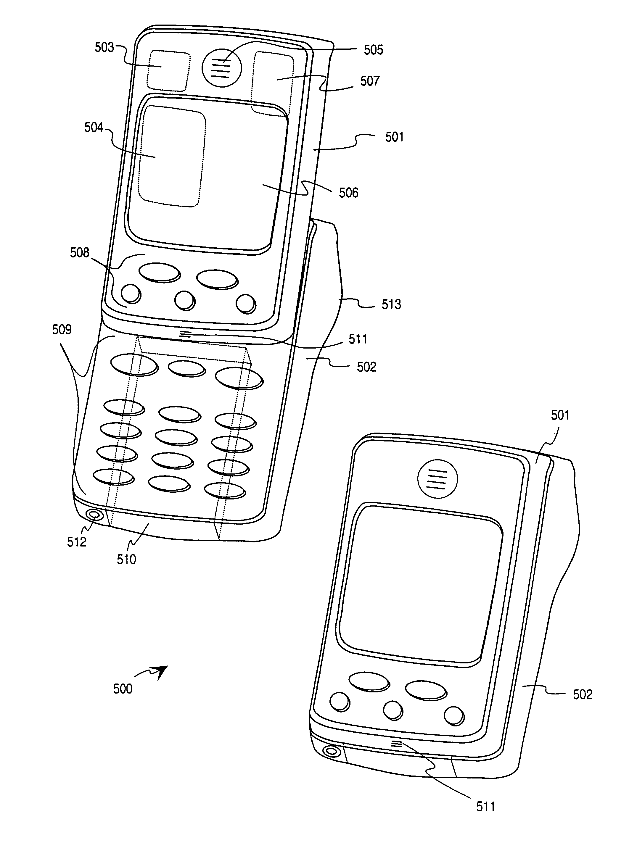
[0043]FIG. 6a illustrates schematically a telephone device according to an advantageous embodiment of the invention in a retracted configuration where a relatively large portion of a body part 601 is within a sleeve-like grip part 602. FIG. 6b illustrates the same telephone device in an extended configuration where the body part has been moved into a longitudinal direction (upwards in the orientation shown in the drawings) so that a larger portion thereof has come out from the grip part. FIG. 6b shows the exemplary locations of a loudspeaker 603, a display 604 and a keypad 605 within the body part, and the exemplary locations of a locking mechanism release button 606 and a microphone 607 within the grip part.

[0044]We may define that the sleeve-like grip part 602 is generally limited by front and back surfaces, two parallel side surfaces and a bottom surface. The front surface is the one which covers the keypad 605 in the retracted configuration, and the back surface is the one which...


PUM


Abstract

A telephone apparatus comprises a body part (601) and a sleeve-like grip part (602) mounted to the body part (601) for longitudinal slidable movement between a retracted position and an extended position. Mechanically coupled to the body part (601) and the grip part (602) there is a spring (700, 1203) for effecting the longitudinal slidable movement. A locking mechanism (1004, 1006, 1007) is provided for detachably locking the body part and the grip part into the retracted position. There is also a user-actuatable releasing actuator (1005) for releasing the locking mechanism. The releasing actuator (1005) is located within the grip part (602).

Description

TECHNOLOGICAL FIELD[0001]The invention relates in general to the electromechanical structure of a telephone apparatus. Especially the invention relates to the selection, form and mutual arrangement of the structural components of a telescopically extendable telephone apparatus. The term telephone apparatus is understood to mean a piece of communication equipment a normal operational position of which is one where a human user holds the device in question with one hand against the side of his head.BACKGROUND OF THE INVENTION[0002]Telescopic or other extendable structures are provided for telephone apparatuses in order to make the device physically small in a transport position and to bring the loudspeaker and microphone thereof close enough to the ear and mouth respectively of a human user in an operational position. FIGS. 1 to 5b illustrate some prior art structures of this kind. The mobile telephone 100 of FIG. 1 comprises a body part 101 and a microphone arm 102 which is rotatably...

Claims


Application Information

Patent Timeline
Patent Type & Authority Patents(United States)
IPC IPC(8): H04N9/00H04M1/02
CPCH04M1/0237
Inventor GRONROOS, MIKA JUHANIPERTTULA, AULISKAUHANIEMI, ILPORONKKO, ANTTISAVOLAINEN, PERTTISUUTARI, JARI
Owner NOKIA MOBILE PHONES LTD
Why Eureka
Try Eureka