Shoulder prosthesis

a shoulder and prosthesis technology, applied in the field of shoulder prosthesis, can solve the problem of not being able to adjust the ball head vis-à-vis the stem,

Inactive Publication Date: 2007-07-03
MATHYS AG BETTLACH
View PDF29 Cites 82 Cited by
  • Summary
  • Abstract
  • Description
  • Claims
  • Application Information

AI Technical Summary

Benefits of technology

[0021]In the case of a single-eccentric development the shoulder bore of the middle section is centred and the conical recess or other connection means is developed eccentric in the ball head. By changing the rotation position of the ball head on the middle section the centre of the ball head can be set relative to the stem end on an orbit the radius of which equals the eccentricity. In conjunction with the setting of the middle section along the first direction a continuous adjustability of the ball head vis-à-vis the stem end in two dimensions thereby results.

Problems solved by technology

Apart from the fact that the ball head is displaced in anterior-posterior direction when clamped to the middle section, the ball head is not adjustable vis-à-vis the stem.

Method used


Image

  • Shoulder prosthesis
  • Shoulder prosthesis
  • Shoulder prosthesis

Examples


first embodiment

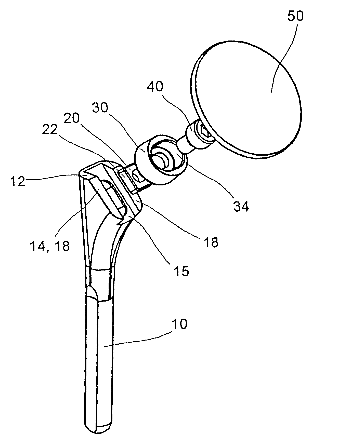
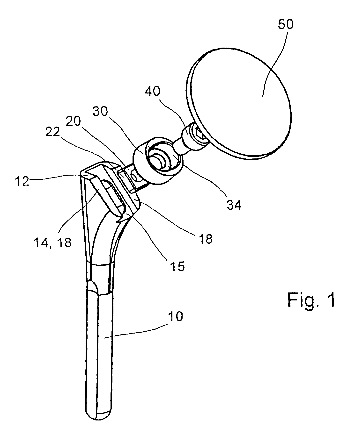
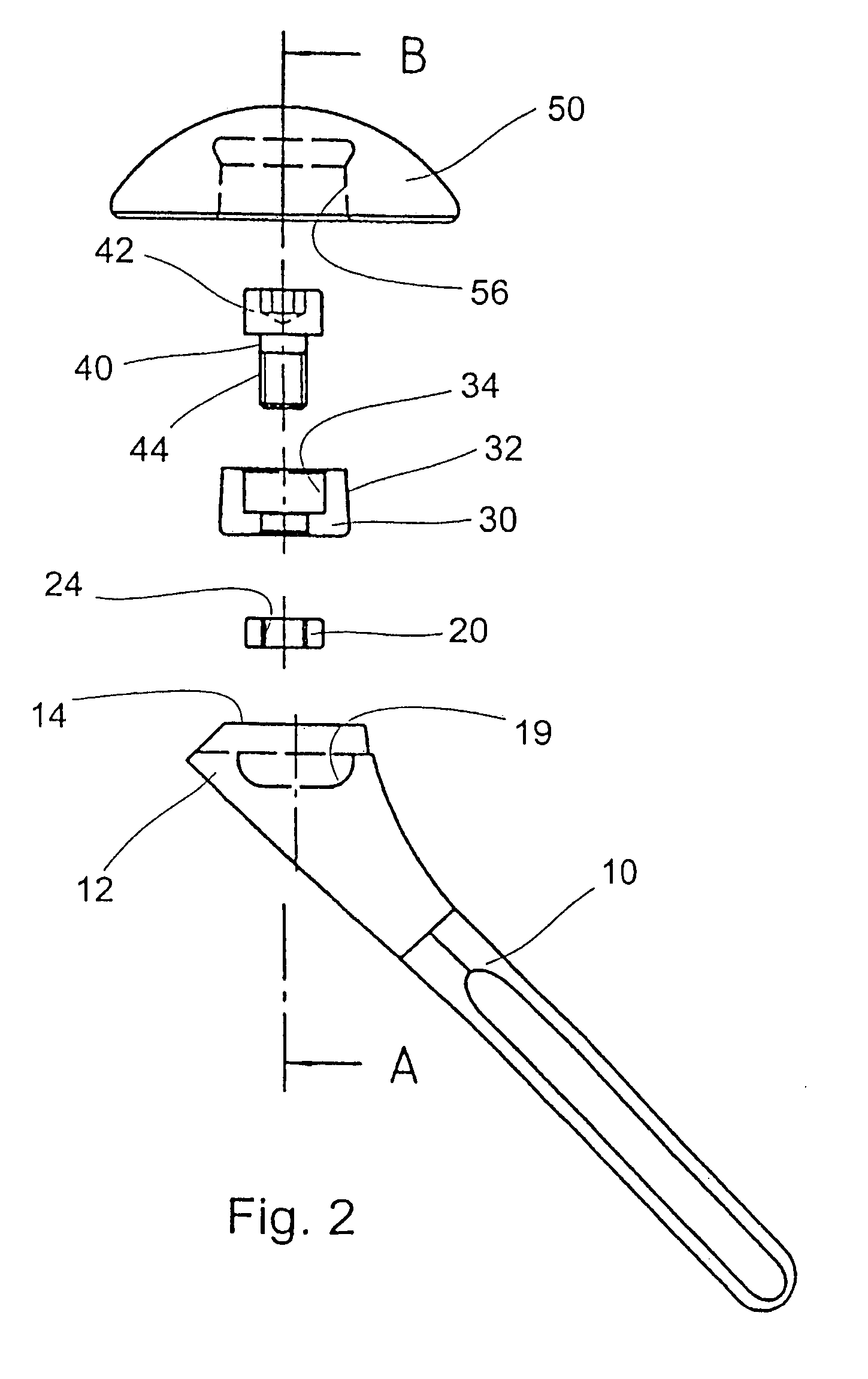
[0039]In the case of the first embodiment the sliding block 20 is guided in a dovetail guide 15, to which end an inwardly-widening groove 16 is developed in the connection surface 14 and two lateral guide surfaces 22 of the overall approximately square sliding block 20 are correspondingly inclined (FIG. 3) with the result that the sliding block 20 is displaceably guided in the groove 16 in lateral-medial direction. Edges 18 stand on both sides of the groove 16 in the connection surface.

[0040]The middle section 30 has a frustum-shaped exterior 32 and an axial slot shoulder bore 34, the longer dimension of the shoulder bore 34 being directed anterior-posterior. The threaded bolt 40 is inserted into the shoulder bore 34 and screwed into a threaded bore 24 of the sliding block 20. The threaded bolt 40 has a head 42 with a hexagon socket and a threaded stem 44 and the head of the threaded bolt 40 is completely housed in the shoulder bore 34. By tightening the threaded bolt 40 the middle ...

second embodiment

[0042]FIG. 5 shows a shoulder prosthesis, similar to that of FIGS. 1 to 4, the shoulder bore 34 being circular however. The middle section 30 cannot therefore be adjusted anterior-posterior. To nevertheless achieve a continuous adjustability in two dimensions, the recess 56 is arranged eccentric in the underside 54 of the ball head 50. The centre of the ball head 50 can therefore be positioned on a circular line around the longitudinal axis of the middle section 30. In conjunction with the medial-lateral adjustability of the middle section 30 at the proximal end 12 of the stem 10 a continuous adjustability is thereby likewise obtained within a surface area large enough to be able to match the anatomical conditions of the individual case.

[0043]The endoprosthesis can be assembled before or after the insertion of the stem 10 into the humeral channel, the threaded bolt 40 being loosely screwed firstly through the middle section 30 into the sliding block 20. The attachment element 20 can...


PUM


Abstract

The shoulder prosthesis has a stem (10), a ball head (20) and a middle section (30) that can be attached to the proximal end (12) of the stem (10) and to which the ball head (50) can be attached. The middle section (30) can be clamped to an attachment element (20) that is adjustable in a first direction at the proximal end (12) of the stem (10), the first direction lying in the resection plane or parallel thereto. The first direction generally runs approximately medially-laterally. The attachment element (20) can be displaceable on the stem (10) by means of a dovetail guide (15) or guided displaceable in a guide bore in the stem (10). The middle section can be clamped against the attachment element (20), whereby the attachment element (20) and the middle section (30) can be fixed.

Description

CROSS-REFERENCE TO RELATED APPLICATION[0001]This application is a continuation-in-part and claims benefit under 35 USC § 120 of PCT Application No. PCT / EP02 / 14634, filed 20 Dec. 2002, incorporated herein by reference, which in turn claims priority from German Patent Application No. 201 20 703.6, filed 21 Dec. 2001, incorporated herein by reference and to which priority is claimed.BRIEF DESCRIPTION OF THE INVENTION[0002]The invention relates to a shoulder prosthesis with a stem, with a ball head and with a middle section that can be attached to a proximal end of the stem at various positions along a first linear direction and to which the ball head can be attached.BACKGROUND[0003]Such a shoulder prosthesis is known from EP-A 0 953 321. The middle section has outwardly-projecting ribs by means of which it can be inserted into a recess at the proximal end of the stem in various laterally-medially staggered positions. The middle section is connected to the stem by a press fit and the ba...

Claims


Application Information

Patent Timeline
Patent Type & Authority Patents(United States)
IPC IPC(8): A61F2/40A61F2/44A61B17/16A61F2/00A61F2/02A61F2/30A61F2/46
CPCA61F2/4014A61B17/1659A61F2/40A61F2/4059A61F2/4612A61F2/468A61F2002/30143A61F2002/30153A61F2002/30322A61F2002/30329A61F2002/30332A61F2002/30387A61F2002/304A61F2002/30401A61F2002/30494A61F2002/30507A61F2002/3051A61F2002/30542A61F2002/30553A61F2002/30555A61F2002/30604A61F2002/30612A61F2002/30617A61F2002/30714A61F2002/30774A61F2002/30777A61F2002/30794A61F2002/30795A61F2002/30797A61F2002/308A61F2002/30807A61F2002/30812A61F2002/30827A61F2002/30884A61F2002/30892A61F2002/4018A61F2002/4029A61F2002/404A61F2002/4044A61F2002/4062A61F2002/4077A61F2002/4631A61F2002/4638A61F2220/0025A61F2220/0033A61F2230/0017A61F2230/0019A61F2250/0008A61F2250/0026A61F2250/0089A61F2250/0097A61F2002/3054A61F2002/3071A61F2002/3079A61F2002/4037
Inventor BLATTER, GEORGESSCHWAGERL, WOLFGANGZENZ, PETERDALLMANN, FRANKGLIEN, WILFRIEDSALMON, DIRKIRLENBUSCH, ULRICH
Owner MATHYS AG BETTLACH
Why Eureka
Try Eureka