

Fluid treating method and apparatus
a treatment method and fluid technology, applied in the direction of sedimentation settling tanks, filtration separation, separation processes, etc., can solve the problems of vacuum-rotating apparatus, dehydration, and respective problems of apparatuses, and achieve high efficiency
- Summary
- Abstract
- Description
- Claims
- Application Information
AI Technical Summary
Benefits of technology
Problems solved by technology
Method used
Image

Examples
first embodiment
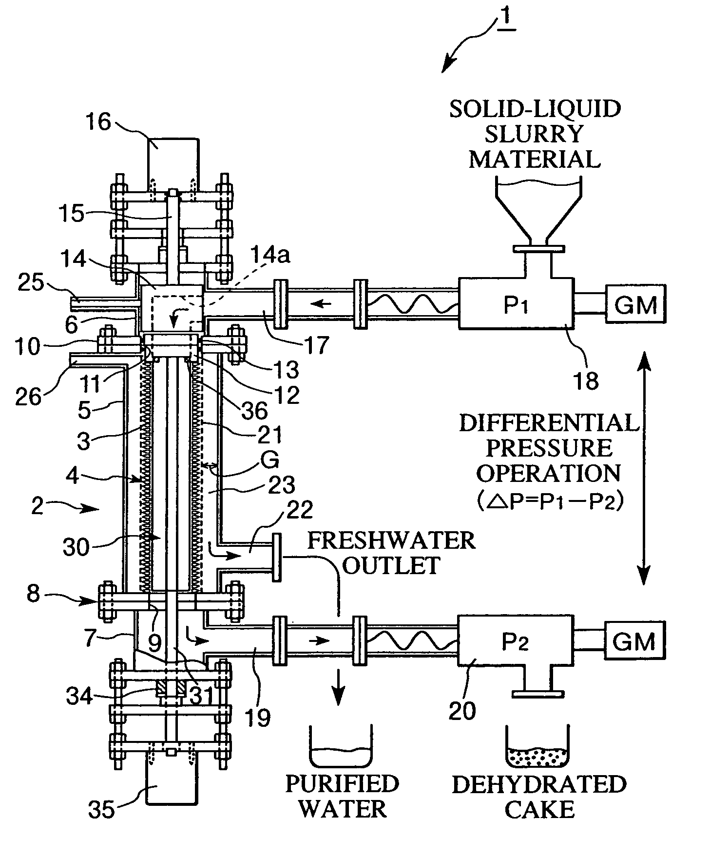
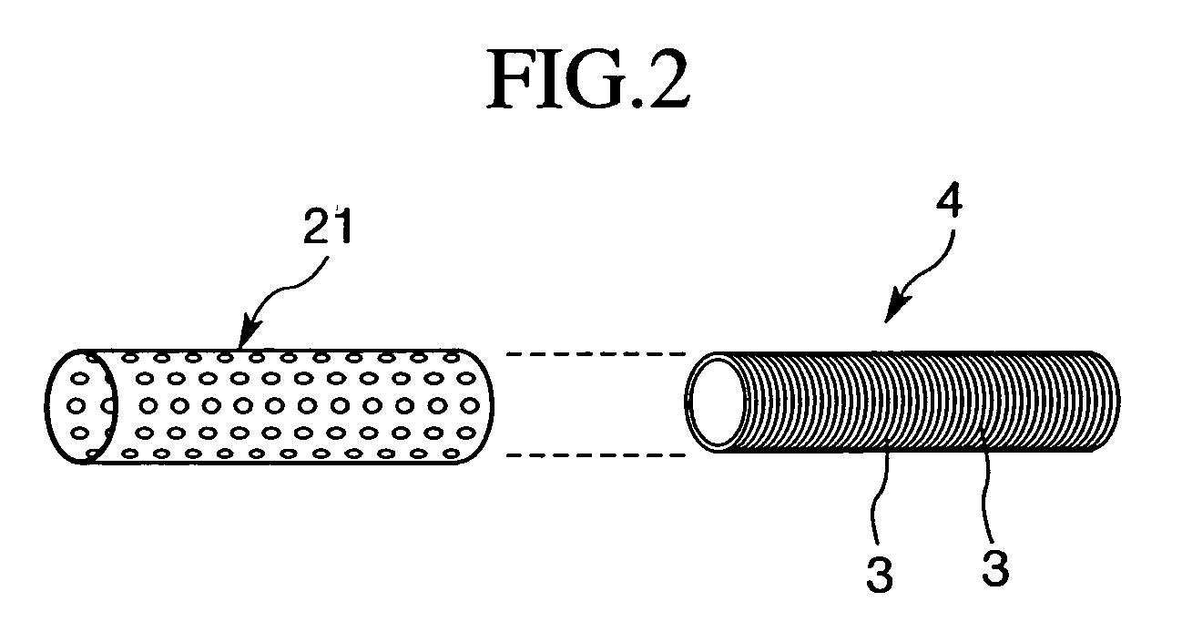
[0048]FIG. 1 illustrates a schematic configuration of an embodiment of the fluid treating apparatus adapted to implement the fluid treating method of the present invention.
[0049]The fluid treating method of the present invention comprises the steps of forming a ring lamination by laminating a plurality of filtering rings with contact surfaces facing each other; pressing the ring lamination under a prescribed pressure in a laminating direction of the filtering rings to closely adhere the contact surfaces; directing an object fluid into gaps formed by contact surfaces of neighboring filtering rings of the ring lamination; and dividing the object fluid into a first separated fraction and a second separated fraction and separating the same.
[0050]According to the method of the present invention, as described later in detail, the surface finishing accuracy of at least the portion of the filtering rings closely adhering to each other and facing each other, i.e., the surface roughness Ra (c...
concrete example
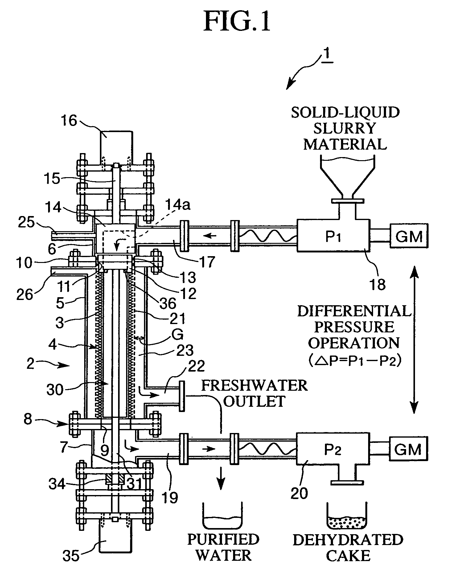
Filtering Ring
[0095]Material: Austenitic stainless steel (SUS304) or titanium
[0096]Thickness (t): 5 mm (stainless steel) or 1 mm (titanium)
[0097]Inside diameter (d1): 136 mm
[0098]Outside diameter (d2): 156 mm
[0099]Inner peripheral radius (r1): 3 mm
[0100]Outer peripheral radius (r2): 1 mm
[0101]Wedge angle (α): 60°
[0102]Finishing accuracy (Ra): 20 μm
Ring Lamination
[0103]Number of filtering rings in lamination: 160 to 800 rings
Operating Conditions
[0104]Fixed ring pressure (contact surface pressure (p)): 8 to 177 kg / cm2
[0105]Object fluid supply pressure P1: 10 to 60 kg / cm2
[0106]Object fluid suction pressure P2: 10 to 60 kg / cm2
[0107]Pressure during filtering ΔP: 10 to 60 kg / cm2
Properties of Object Fluid
[0108]A water-containing suspension (solid-liquid slurry) having a solid-liquid ratio of 1:3, containing powdery inorganic solids of a particle size of about 0.5 to 50 μm was employed.
[0109]The fluid treating method and the fluid treating apparatus of the present invention is applicable...
second embodiment
[0113]Another embodiment of the filtering ring 3 is illustrated in FIG. 8. In the first embodiment, surfaces of the filtering rings 3 facing each other are flat. In the filtering rings 3 of the second embodiment, an annular concave groove 51 is formed on one surface, and an annular convex projection 52 capable of engaging with this concave groove 51 is formed on the other surface.
[0114]When laminating the filtering rings 3, therefore, in two neighboring filtering rings 3, the convex projection(s) 52 formed on one filtering ring can fit into the concave groove(s) 51 of the other filtering ring, thus extending the channel for object fluid formed by the neighboring filtering rings 3.
[0115]In this configuration, the pressure difference between the inside and outside of the ring lamination 4 becomes larger, thus resulting in improved separation accuracy.
[0116]When using filtering rings 3 of such a shape, the convex projection(s) 52 formed on one filtering ring 3 fit the concave groove(s)...
PUM
| Property | Measurement | Unit |
|---|---|---|
| Length | aaaaa | aaaaa |
| Length | aaaaa | aaaaa |
| Length | aaaaa | aaaaa |
Abstract
Description
Claims
Application Information