Pot and pan washing machine, components, and methods of washing items

a technology of washing machine and components, applied in the direction of cleaning using liquids, tobacco, liquid fuel engines, etc., can solve the problems of reducing efficiency and performance, affecting the overall efficiency and performance of the machine, and fluid will take, so as to reduce the potential for items, less turbulence, and efficient pump operation

Inactive Publication Date: 2007-07-24
UNIFIED BRANDS
View PDF3 Cites 21 Cited by
  • Summary
  • Abstract
  • Description
  • Claims
  • Application Information

AI Technical Summary

Benefits of technology

[0013]In the preferred embodiment of the instant invention, number of holes (i.e. the void concentration) increases as the distance from the pump inlet increases. This results in a more uniform, and minimal, vacuum across the entire length of the intake which eliminates the potential for items, such as small lids, small trays, dish towels, etc., to be sucked down and held against the surface of the intake. As there will always be some difference in pressure at the voids there will never be a true “zero vacuum”; however the pattern of the instant invention comes very close.
[0014]Another important benefit of the varying hole concentration of the instant invention is that the pattern helps to create a linear “chute” for the water to travel through prior to entering the pump. This helps align the water to create a more laminar flow into the pump, thus creating less turbulence, which results in more efficient pump operation.
[0015]In a preferred embodiment of the instant invention, a minimum void concentration is provided near the suction source (the intake manifold inlet). This minimum void concentration is provided to eliminate swirling (whirlpool or eddy) that is created when the jets of the washing machine introduce fluid to an area in which no fluid is removed.
[0016]An additional feature of a preferred embodiment of the instant invention is the inclusion of a maximum void concentration within a predetermined area. The purpose of the maximum void concentration is to prevent items, such as dish towels, from sticking to the intake manifold during operation. The maximum void concentration for an area is based upon the amount of suction that is desired across that area. Thus, as the suction from the pump decreases as the distance from the intake inlet increases, the maximum void concentration will increase for a given surface area. In addition to the maximum void concentration, the voids of the intake manifold of a preferred embodiment have a maximum area to prevent small items and debris from being drawn into the intake manifold.

Problems solved by technology

Although the prior art pot and pan washing machine disclosed in U.S. Pat. No. 4,773,436 provides an exceptional wash action, many of the components discussed above hinder the overall efficiency and performance of the machine.
Nevertheless, the improved intake manifold itself has several disadvantages that result in a reduction of efficiency and performance.
The main problem with the prior art pump intakes in a pot washing system is that a fluid will take the path of least resistance to the inlet of the pump.
This “sucking” action creates problems in pot and pan washing systems as it will eventually draw the wares toward the intake-end of the wash sink (a phenomenon called “pan migration”) where they can potentially “pile up”, blocking the inlet manifold and starving the pump by restricting the fluid flow to the inlet.
This too reducing the efficiency and performance of pump 150.
Although a machine that employs a wash tank and jet stream of the type described above is extremely useful for washing pots and pans, it is less desirable for washing smaller items such as utensils.
In addition, it is difficult to separate items that require different levels of cleansing within the single wash tank of the above-described washing machine.
Although the powered utensil basket does provide a segregated washing area for utensils and other items that is removable from the washing machine, the basket itself is rather bulky and often not utilized in operation.

Method used


Image

  • Pot and pan washing machine, components, and methods of washing items
  • Pot and pan washing machine, components, and methods of washing items
  • Pot and pan washing machine, components, and methods of washing items

Examples


Embodiment Construction

[0025]Referring to the drawing figures, therein is shown an optimum form of the subject pot and pan washing machine with essentially all features usable to increase performance, versatility and efficiency therewithin. Preferred embodiments of the present invention are hereinafter described with reference to the accompanying drawings.

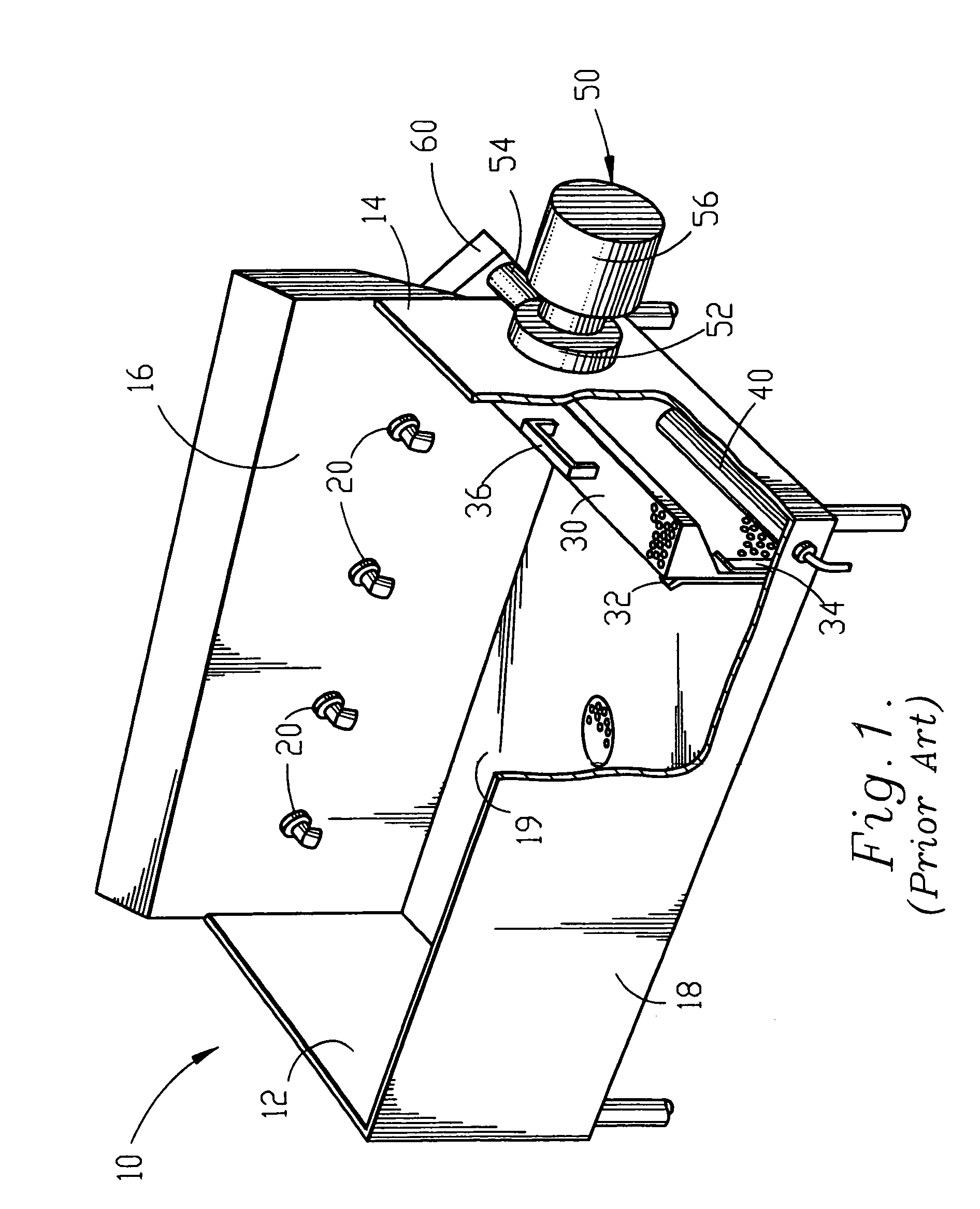
[0026]The operation of the pot and pan washing machine described hereinafter is substantially similar to the operation of the prior art machine described above. The instant invention provides significant features that increase the performance, versatility and efficiency of the pot and pan washing machine.

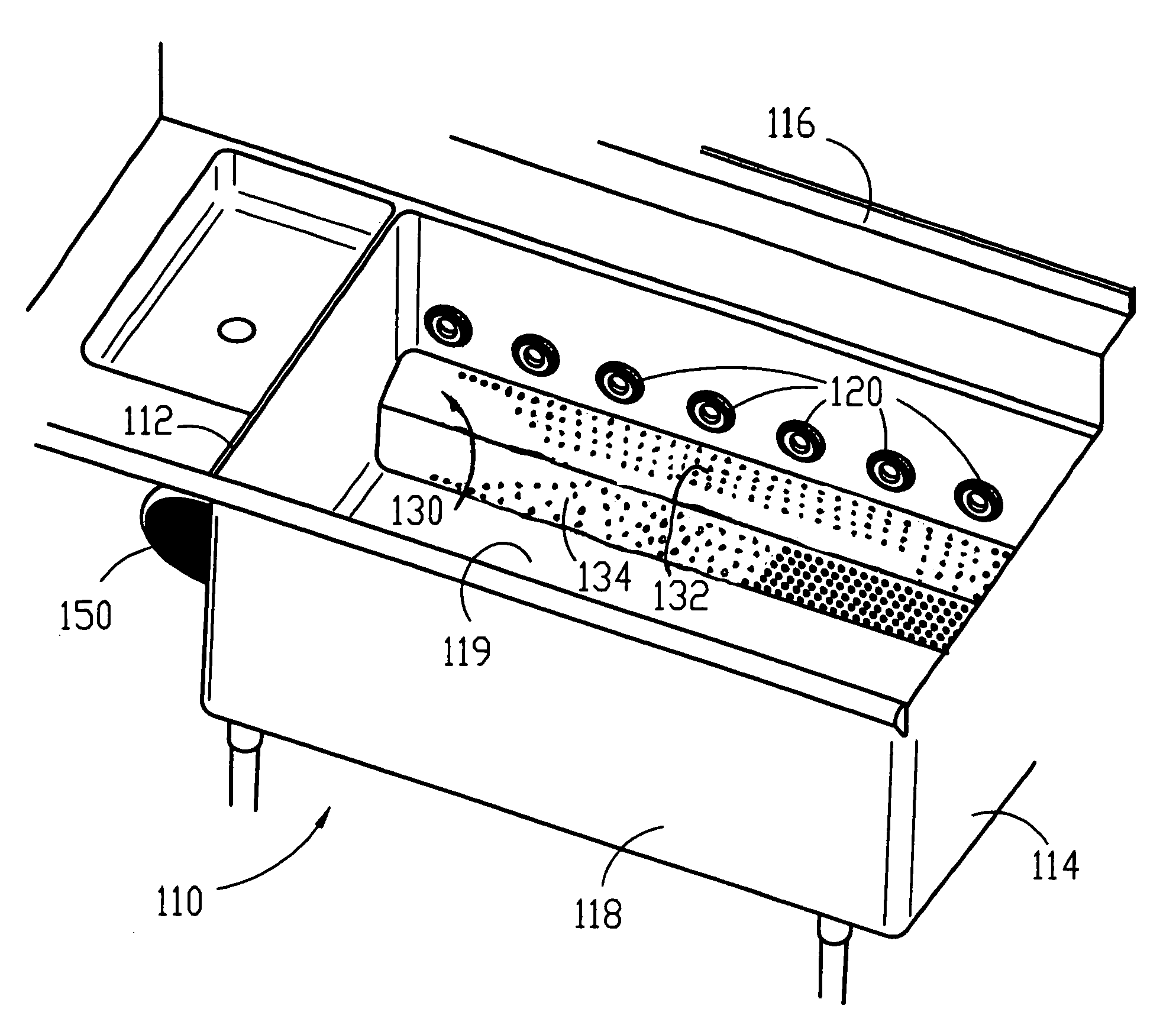
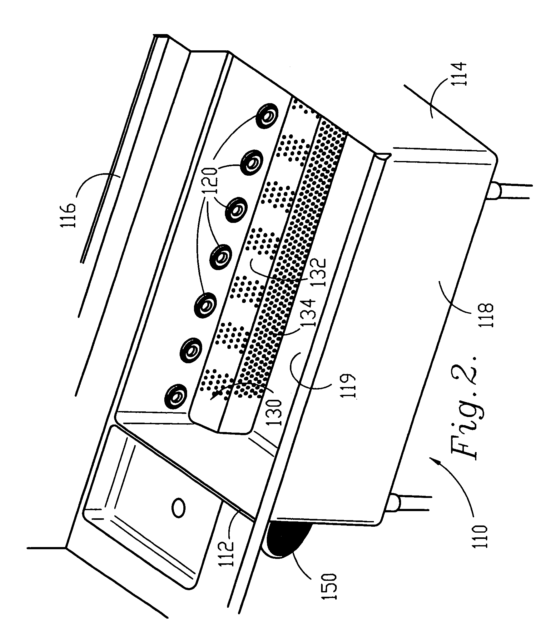
[0027]Referring to FIG. 3, a preferred embodiment of the wash tank of the inventive pot and pan washing machine is shown. The wash tank / basin of the instant invention is constructed in essentially the same manner as the wash tanks of the prior art. Wash tank 110 includes left end wall 112, right end wall 114, rear side wall 116, front side wall 118 and b...


PUM


Abstract

An improved pot and pan washing machine is provided including a low suction intake manifold and a partition for capturing a substantial portion of the wash action of the washing machine within a segregated area. The intake manifold of the instant invention includes a plurality of voids having a void concentration that increases as the distance from the source of suction (such as a pump or intake inlet) increases. The partition (or divider) of the instant invention can be removed and repositioned within the wash tank through the use of channels along the walls of the wash tank that receive the partition.

Description

CROSS-REFERENCE TO RELATED APPLICATIONS[0001]This is a continuation-in-part of U.S. application Ser. No. 09 / 947,484 filed Sep. 6, 2001, now U.S. Pat. No. 6,739,348, and a continuation-in-part of U.S. application Ser. No. 10 / 724,486 filed Nov. 26, 2003, now U.S. Pat. No. 6,976,496 which is a divisional of U.S. application Ser. No. 09 / 947,485 filed Sep. 6, 2001, now abandoned, the disclosures of which are incorporated herein by reference in their entirety.FIELD OF THE INVENTION[0002]The present invention relates to improvements in a pot and pan washing machine. More specifically the present invention relates to improvements within the wash tank portion of a pot and pan washing machine, including an improved intake manifold and, a divider for isolating a portion of the wash tank, and methods for washing pots, pans, utensils and other similar items.BACKGROUND OF THE INVENTION[0003]Pot and pan washing machines, of the type used in restaurants, institutions and other eating facilities oft...

Claims


Application Information

Patent Timeline
Patent Type & Authority Patents(United States)
IPC IPC(8): B08B9/20B08B3/00A47L15/08A47L15/16A47L15/50F04D29/42F04D29/70
CPCA47L15/0092A47L15/08A47L15/16F04D29/708F04D29/426F04D29/4273B08B3/006
Inventor CANTRELL, JOHN W.INCH, JOHNCHURCHILL, MARKSTOCKDALE, DAVECORPENNY, PETER A.
Owner UNIFIED BRANDS
Why Eureka
Try Eureka