Self-cooling ferrfluid seal

a technology of ferrofluid seals and seals, which is applied in the direction of sealing, engine seals, packaging, etc., can solve the problems of heat generation, inability to properly operate the seal, and limitations of each of the listed methods, so as to eliminate the potential for coolant leakage, effective heat flow paths and heat dissipation surfaces

Inactive Publication Date: 2008-03-04
FERROTEC (USA) CORP
View PDF19 Cites 12 Cited by
  • Summary
  • Abstract
  • Description
  • Claims
  • Application Information

AI Technical Summary

Benefits of technology

[0012]It is an object of the present invention to provide a cooling system that eliminates the potential for coolant leaks. It is another object of the present invention to provide a cooling system that has effective heat flow paths and heat dissipation surfaces for both the stationary and rotating elements of the ferrofluid seal. It is yet another object of the present invention to generate effective airflow paths within the ferrofluid seal so that both its stationary and rotating elements can be cooled by forced convection. It is a further object of the present invention to provide airflow inside the seal to provide effective cooling to both the stationary and rotating elements of the seal. It is yet a further object of the present invention to provide a cooling system that provides cooling simultaneously when the seal is operated and where the cooling effect increases proportionally with the operating speed of the seal.
[0018]The cooling effect of the present invention occurs simultaneously with the operation of the ferrofluid seal. As the rotation speed increases, so does the cooling effect. This effectively balances the viscous heat generation of the magnetic fluid.

Problems solved by technology

Heat generation has been a common problem for ferrofluid seals that operate at high speed.
The viscous heat generated by the magnetic fluid tends to heat up the seal to a level that does not allow for the proper operation of the seal.
Each of the listed methods has limitations.
The natural convection cooling method is frequently unable to provide enough cooling effect, and the seal has a tendency to overheat at high speeds.
The externally introduced forced air convection method requires additional space and parts to integrate the fan, which introduces design problems and higher costs.
Further, the internal components are difficult to be cooled by this method.
When water or other liquid coolant is used, there is always the concern that the liquid coolant may leak out of the cooling channels and cause equipment damage and process contamination.
The use of Peltier devices adds additional cost, space and parts to integrate these Peltier devices and further requires power to be supplied to the Peltier devices to effect cooling.

Method used


Image

  • Self-cooling ferrfluid seal
  • Self-cooling ferrfluid seal
  • Self-cooling ferrfluid seal

Examples


Embodiment Construction

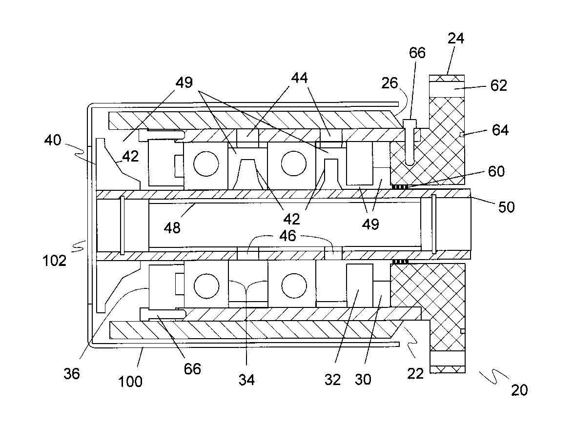
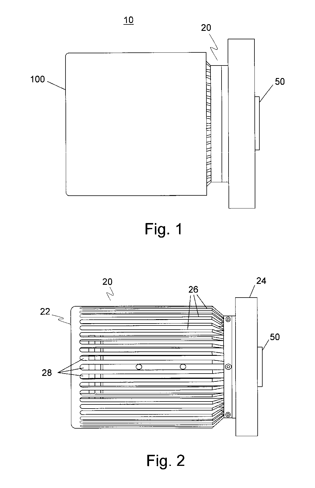
[0025]The preferred embodiment of the present invention is illustrated in FIGS. 1-4. FIG. 1 illustrates an air-cooled, ferrofluid seal device 10. Ferrofluid seal device 10 includes a seal housing 20, a rotatable shaft 50 and an optional cover 100. Turning now to FIG. 2, there is illustrated seal housing 20 and rotatable shaft 50. Seal housing 20 includes a housing case 22 and a pole piece 24 securely attached to housing case 22. Housing case 22 is made of a heat conducting material, preferably copper, forming a good heat flow path for pole piece 24. Housing case 22 has a plurality of fins 26 and case vent channels 28. The plurality of fins 26 provides an effective heat dissipation surface.

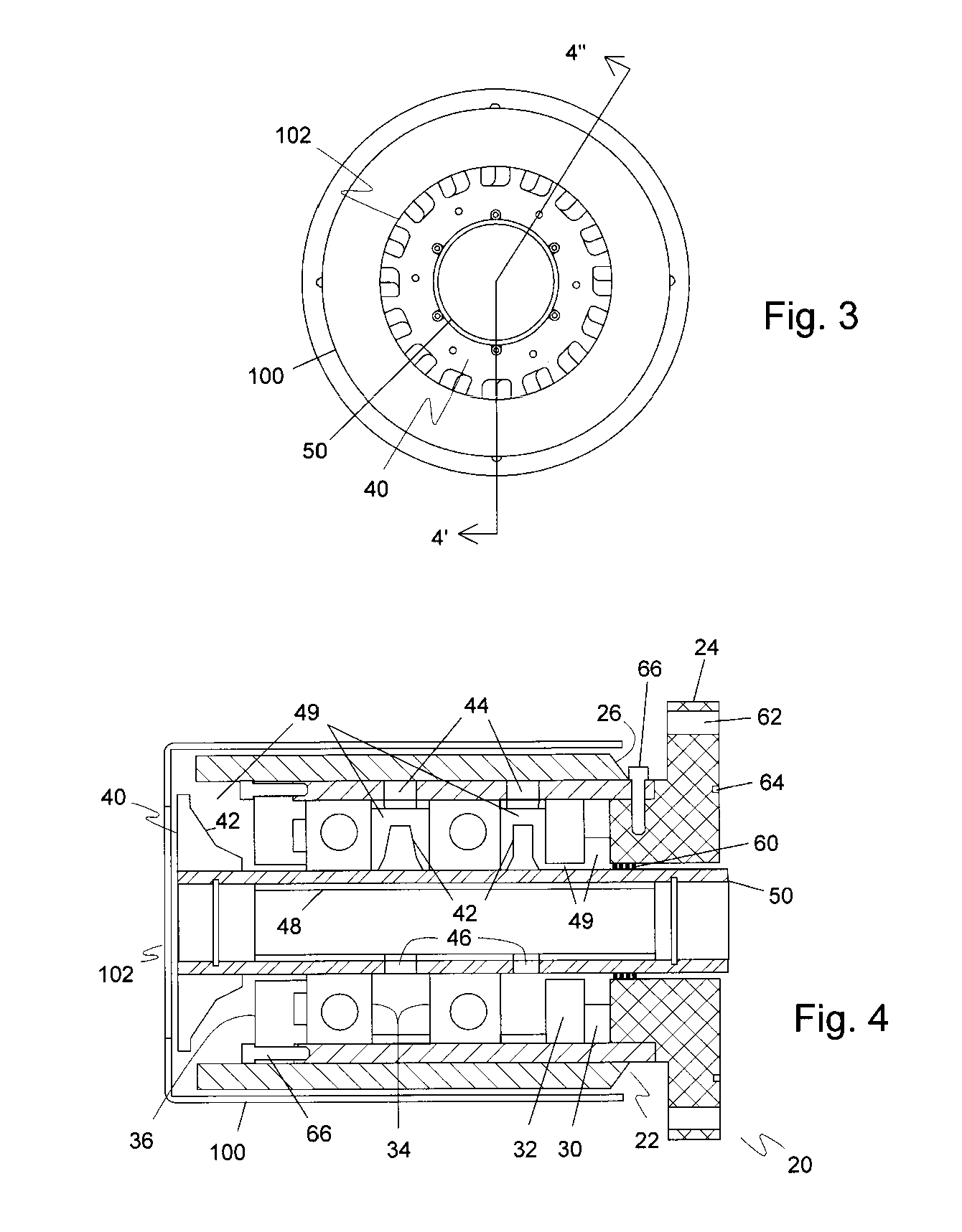
[0026]FIG. 3 illustrates an end view of ferrofluid seal device 10 showing the rotatable shaft 50, cover 100 and cover end opening 102. Shaft end fan blade 40 is seen through cover end opening 102 securely attached to rotatable shaft 50. Line 40′-40″ indicates the cross-sectional view of ferrofluid ...


PUM


Abstract

A self-cooling ferrofluid seal includes a housing having a housing case and an external pole piece integrally connected to the housing case where the housing case has a plurality of heat dissipating surfaces, a magnetic circuit within the housing formed in conjunction with the external pole piece, a rotatable shaft having one or more fan blades where the rotatable shaft is coaxially aligned within the housing, and a quantity of magnetic fluid between the rotatable shaft and the external pole piece forming a ferrofluid seal.

Description

[0001]This application claims the benefit of U.S. Provisional Patent Application No. 60 / 604,673, filed Aug. 26, 2004.BACKGROUND OF THE INVENTION[0002]1. Field of the Invention[0003]The present invention relates generally to the cooling of ferrofluid seals. Particularly, the present invention relates to self-cooling ferrofluid seals.[0004]2. Description of the Prior Art[0005]Ferrofluid seals are widely used in industry. Typically, a ferrofluid seal contains a magnetic circuit that is composed of stationary elements such as magnets and pole pieces, and a rotating element such as a shaft. Magnetic fluid is confined between the rotating and stationary elements by the magnetic field of the magnet and formed into a series of liquid O-rings, which provide sealing.[0006]Heat generation has been a common problem for ferrofluid seals that operate at high speed. The viscous heat generated by the magnetic fluid tends to heat up the seal to a level that does not allow for the proper operation of...

Claims


Application Information

Patent Timeline
Patent Type & Authority Patents(United States)
IPC IPC(8): F16J15/43
CPCF16J15/43Y10S277/93
Inventor LI, ZHIXIN
Owner FERROTEC (USA) CORP
Why Eureka
Try Eureka