
Systems and methods for continuous motion registration distribution with Anti-backlash and edge smoothing

Inactive Publication Date: 2005-06-23
XEROX CORP
View PDF4 Cites 5 Cited by
  • Summary
  • Abstract
  • Description
  • Claims
  • Application Information

AI Technical Summary

Benefits of technology

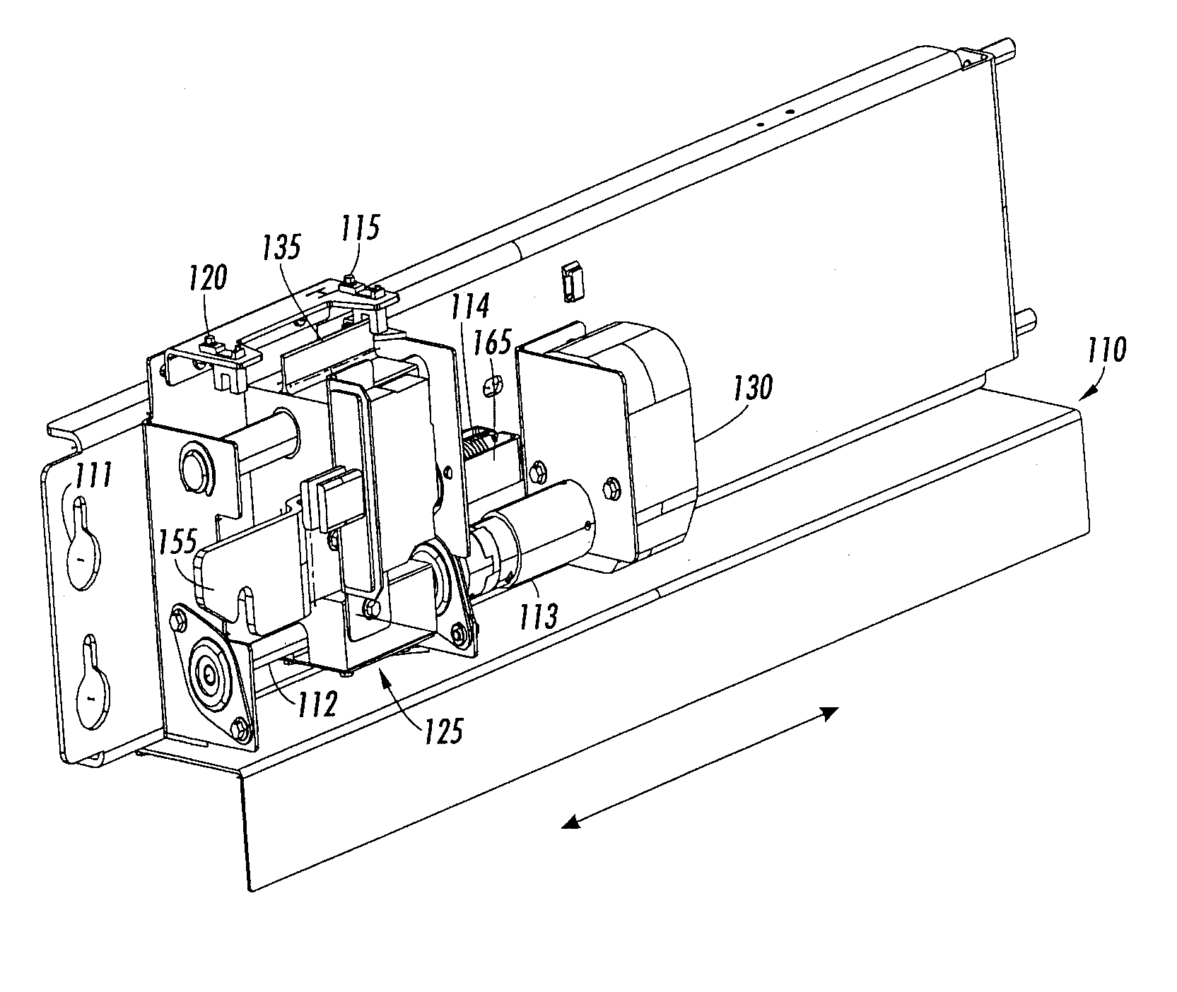
[0010] To address the problem of edge wear on fuser rolls, a registration distribution system is disclosed in which no prior knowledge of paper size is required and the axial motion of the rolls is continuous. By continuously moving the fuser assembly, differential gloss artifacts due to repetitive stress concentrations are spread out over a greater area thereby maximizing roll life with no dependence on paper size. Furthermore, continuously moving the fuser assembly eliminates the potential for banding caused by a stepping-type registration distribution system.
[0011] In an exemplary embodiment of the invention, the length of a fuser roll may be increased to allow even the largest paper size to have full travel across the roll area. In another exemplary embodiment, edge effects due to lead screw backlash are reduced by a mechanical system, such as a spring. In yet another exemplary embodiment of the invention, an edge smoothing algorithm is also employed in the invention to further reduce the perception of edge wear.

Problems solved by technology

Such artifacts become visible to the customer after only a few thousand prints have passed through the fuser, far short of the target life of the roll.
However, this method is not always practical or in keeping with existing program goals.
For example, if only one paper size is run for a given roll set, the edge wear exists, but is outside the normal visible area of the print and goes un-noticed.
However, by restricting lateral movement of the fusing station as described, productivity may be slowed due to the necessity to move to the fusing station during a print operation, such as when the pre-set volume of copies have been fused.
Furthermore, banding may also result from the use of such discrete stepping systems.
These and other known methods have drawbacks which severely limit any performance benefits from existing registration distribution systems.
For example, by moving the fusing station only between copy runs or interframes a pre-set distance, the fuser roller will suffer unnecessary wear at the point where the edges of the sheets contact the roll surface.

Method used


Image

  • Systems and methods for continuous motion registration distribution with Anti-backlash and edge smoothing
  • Systems and methods for continuous motion registration distribution with Anti-backlash and edge smoothing
  • Systems and methods for continuous motion registration distribution with Anti-backlash and edge smoothing

Examples


Embodiment Construction

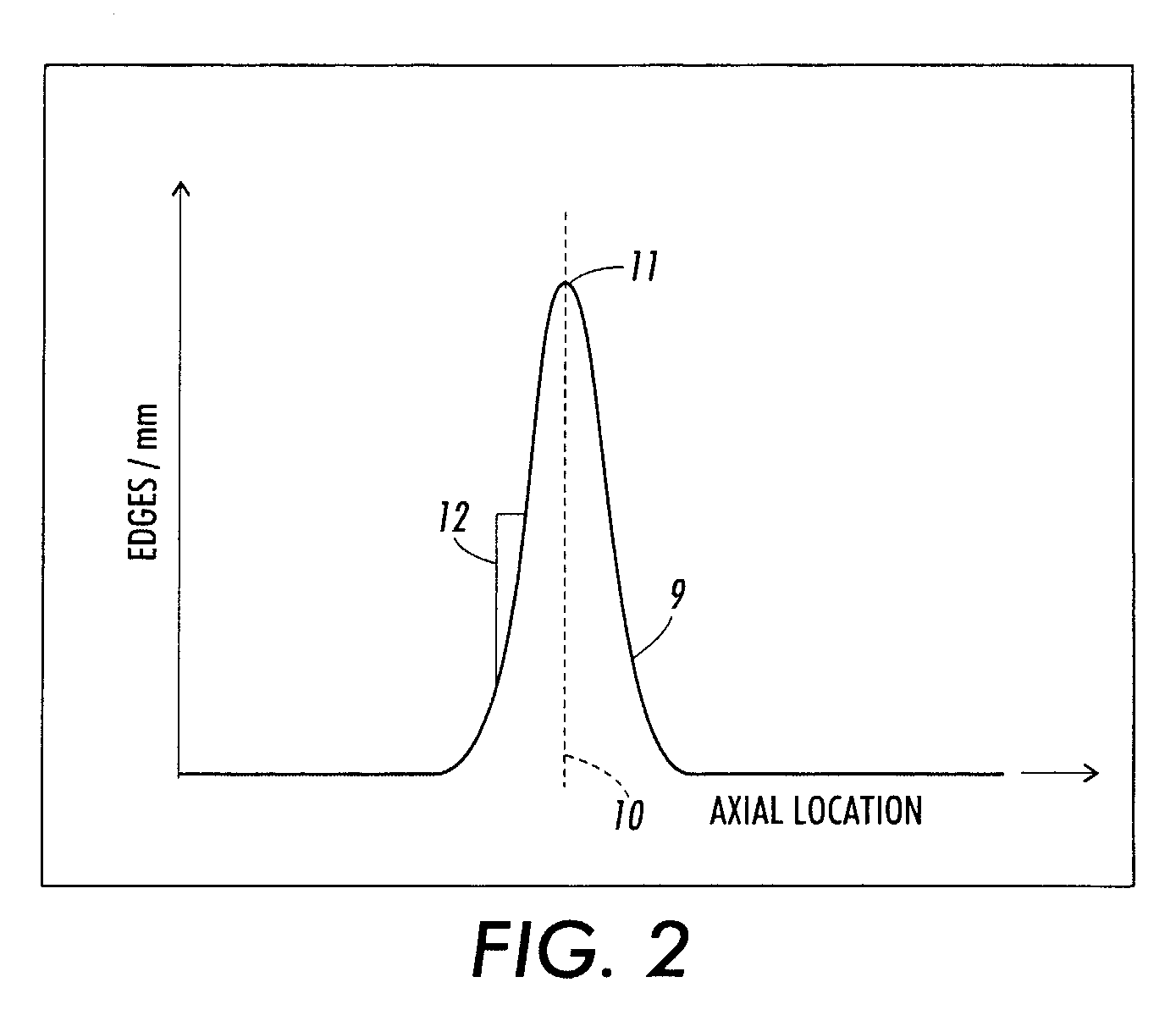
[0028]FIG. 2 is a graph of experimental results showing the relationship between the total number of sheets processed and measured differential gloss levels representing conformable fuser roll wear in a printing system without a registration distribution system. The graph represents onset of edge wear in a printing system without a registration distribution system and the determination of perceivable (differential) gloss. As sheets pass through a nip formed between a conformable fuser roll surface and a non-conformable pressure roll surface near the registration location 10, the sheets are normally distributed according to the accuracy of the paper registration system upstream of the fuser.

[0029] Over a period of time, the distribution of conformable fuser roll wear grows to look like the diagram in FIG. 2, wherein the area under the curve 9 represents the total number of sheets passed through the nip. An example of a way in which edge wear is perceived is at the peak 11 when a cer...


PUM


Abstract

A reprographic marking device has two rolls, e.g., a pressure roll and a fuser roll, forming a nip. A drive motor moves the rolls in a continuous back and forth lateral motion to change the position of the rolls relative to a paper sheet passing through the nip portion.

Description

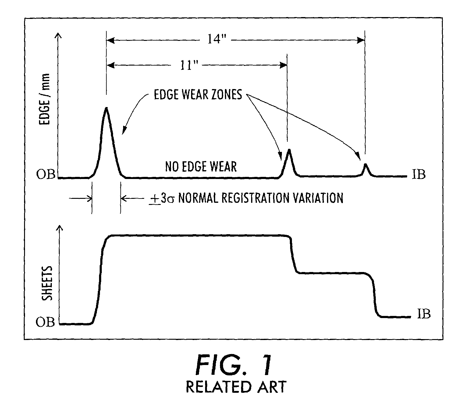
BACKGROUND OF THE INVENTION [0001] 1. Field of Invention [0002] The invention relates generally to a reprographic fusing device for fixing a toner image to a substrate. More specifically, the invention relates to a fusing device that is continuously movable relative to the print medium during printing. [0003] 2. Description of Related Art [0004] In electrostatic printing, a dry marking material, such as toner, is fused to a substrate, such as a paper sheet. Fusing occurs when the substrate is subjected to pressure and / or heat to permanently affix the marking material to the substrate. Most common electrostatic printers use a fuser roll and a pressure roll that form a nip for the substrate to pass through. In many such printers, a variety of different size sheets may be passed through the nip of the rollers. [0005] All conformable rolls suffer from surface wear, especially where the edges of the sheets contact the roll surface. FIG. 1 shows how the edges and body of 11″ and 14″ sheet...

Claims


Application Information

Patent Timeline
IPC IPC(8): G03G15/20B65H5/06G03G15/00
CPCG03G15/2064
Inventor RUSSEL, STEVEN M.HAUMAN, DEWEY H.HANFLAND, JULIE M.SCHENK, RICHARD C.
Owner XEROX CORP
Learn More