Automated optical disk loading rack

an automatic and rack technology, applied in the field of automatic optical disc loading rack system, can solve the problems of requiring significant manual organizing, affecting the efficiency of disc management, and affecting the operation of disc drives, so as to eliminate the potential for scratches, reduce the cost, and simplify the effect of upgrading to newer disc drives

Inactive Publication Date: 2010-07-15
MAKANAWALA TEJESH C
View PDF0 Cites 5 Cited by
  • Summary
  • Abstract
  • Description
  • Claims
  • Application Information

AI Technical Summary

Benefits of technology

[0007]It is another object of the invention to use a disc drive mounting scheme that allows installation of an off the shelf disc drive, thus upgrading to newer versions of disc drives becomes simple and cost effective.
[0008]In accordance with the present invention, there is provided a disc media holder rack and 2 moving disc drives. The disc drives are moved to where the disc media are located, and are directly placed into the disc drive. By loading directly, the need for an intermediary transfer robotic mechanism is eliminated. This disc media are held from the top via vacuum, and are released by gravity after a vacuum leak situation is created. Holding the wafers from the top via vacuum eliminates the potential for possible scratches and the need for additional disc media protection covers. The disc drives used are standard ones used in the computer industry, and the drive mount complies with the standard one in the computer industry. This allows easy upgrade of the equipment from from DVD drives to Blue-ray or HD-dvd disc drive for example.

Problems solved by technology

Ever since discs have been used for data, audio and video storage, managing discs has not been very efficient.
This is an issue for both consumers and businesses.
The discs are stored in cupboards and requires significant manual organizing.

Method used


Image

  • Automated optical disk loading rack
  • Automated optical disk loading rack
  • Automated optical disk loading rack

Examples


Embodiment Construction

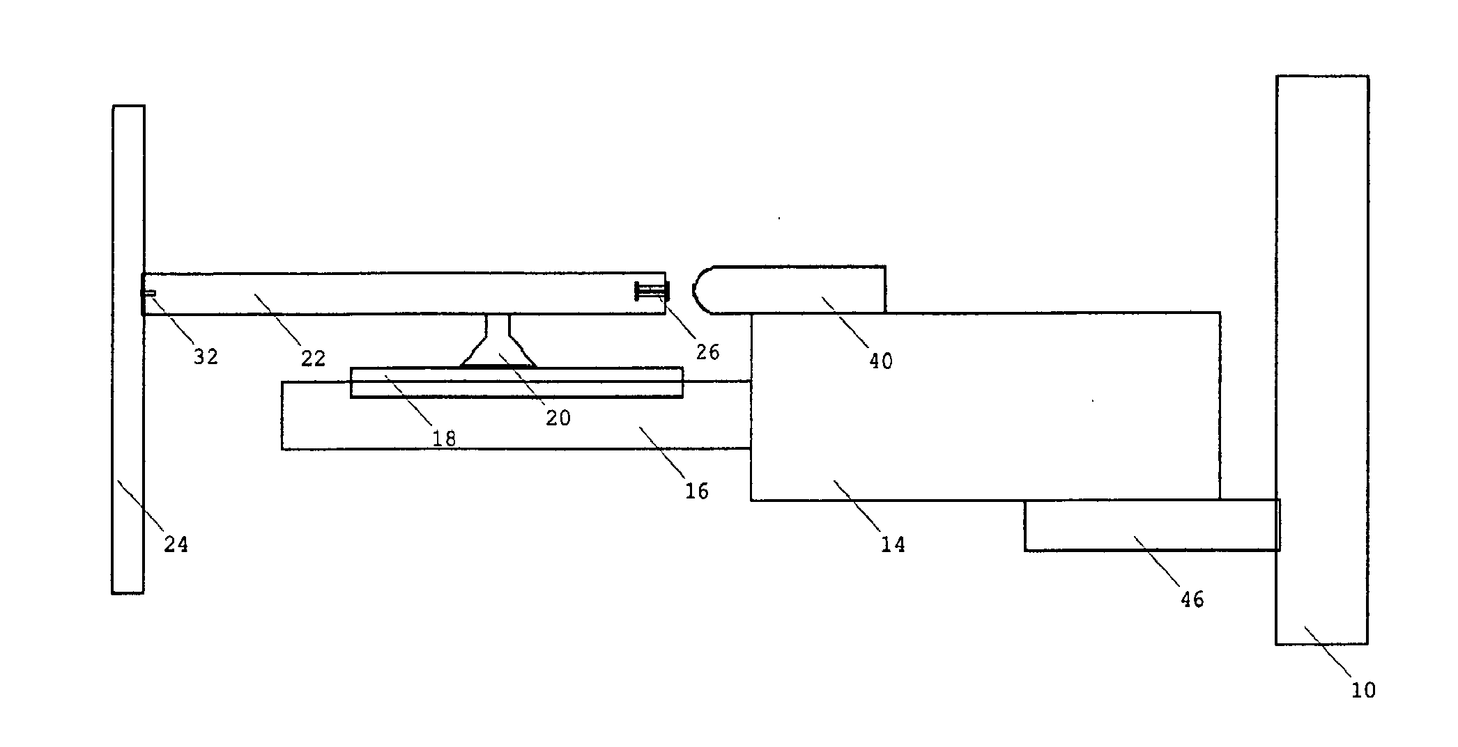
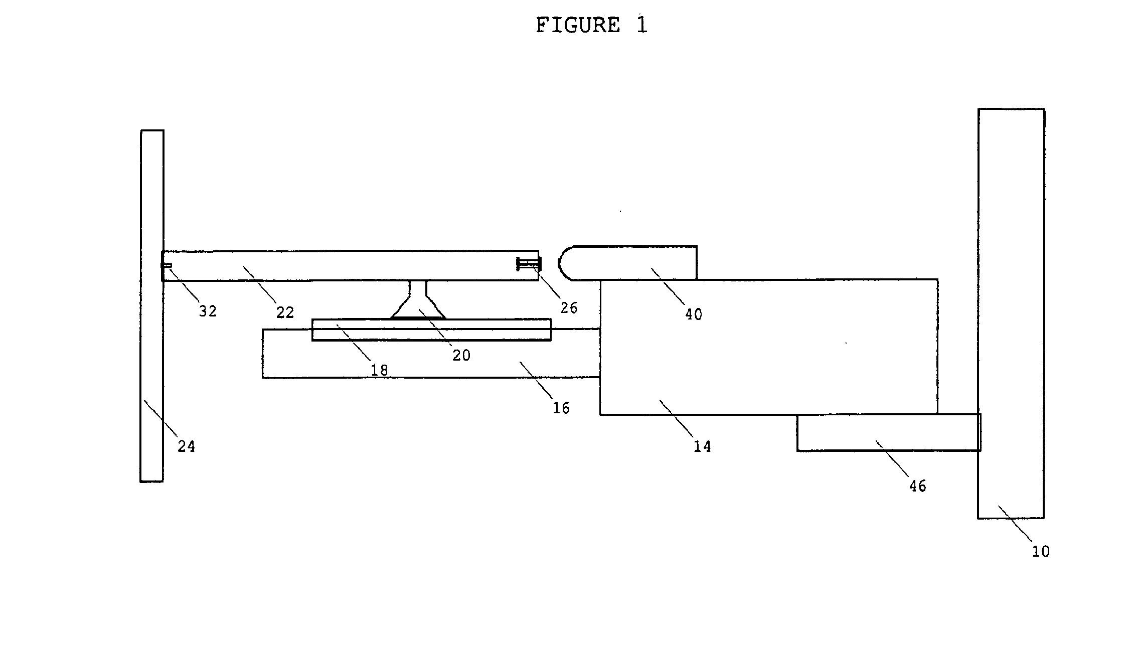
[0016]FIG. 1 is a front partial view of a disc holding rack and moving disc loader. the left most vertical bar shown in the main vacuum rod 24. the left section shows the main vacuum rod 24 attached with one individual vacuum rod 22. both the main vacuum rod 24 and the individual vacuum rod 22 are hollow, and are generally in vacuum. the individual vacuum rod 22 has three potential sources of air inlet, though the one connected to the main vacuum rod 24 is blocked via a check valve 32. the remaining two inlets are temporarily blocked via the spring loaded leak vacuum pin 26 and the disc media 18 holding suction cup 20. the right most vertical bar shown is the vertical lead screw 10. the right section shows the disc drive 14 mechanically connected to vertical lead screw 10 with a drive mount 46. the disc drive 14 is shown in a loading position, where the suction cup 20 was just attached to the disc media 18 that resides in the disc holder 16. above the disc is the leak magnet solenoi...


PUM

PropertyMeasurementUnit
suctionaaaaaaaaaa
gravityaaaaaaaaaa
vacuumaaaaaaaaaa

Abstract

A disc holder (16) rack and 2 moving disk drives (14). The disk holder (16) holds disks (18) from top via vacuum. The discs (18) get released by air entering the vacuum area, thus pushing the disc (18) down. The other part of the invention is the disc drive (14) that is mounted on a vertical drive mechanism (10, 46). By mounting the disc drive (14) directly on the vertical drive mechanism (10, 46), the intermediate transfer robot is eliminated. The drive mount(46) complies with the standard one in the computer industry, thus upgrading disc drives (14) is simplified.

Description

FIELD OF THE INVENTION[0001]The present invention relates to the design of an automated optical disc loading rack system and, more particularly, to how the design simplifies the loading and unloading of optical discs into an optical drive process, while allowing upgradability of drive as advances in drive technology continue.BACKGROUND OF THE INVENTION[0002]Ever since discs have been used for data, audio and video storage, managing discs has not been very efficient. This is an issue for both consumers and businesses. The discs are stored in cupboards and requires significant manual organizing.[0003]Most common solution for audio discs in the consumer market is the 6 disc CD changer, and more recently the conversion of CD data into MPEG files for storage in IPOD style MP3 players.[0004]The solutions in existence may be adequate for audio storage, but data storage for business and video storage for consumers require greater storage capacity.[0005]It is therefore an object of the inven...

Claims


Application Information

Patent Timeline
Patent Type & Authority Applications(United States)
IPC IPC(8): G11B17/04
CPCG11B17/30G11B17/225
Inventor MAKANAWALA, TEJESH C.
Owner MAKANAWALA TEJESH C
Why Eureka
Try Eureka