Bandage type sensor arrangement and carrier assembly therefore, and method of manufacture

Inactive Publication Date: 2009-04-09
MEDILITY
View PDF61 Cites 2 Cited by
  • Summary
  • Abstract
  • Description
  • Claims
  • Application Information

AI Technical Summary

Benefits of technology

[0007]Although the nodule type bandage sensor arrangement is sat

Problems solved by technology

As the sensors are reduced in size, it becomes more difficult to attach the sensors to the body, particularly if the sensors are in the for

Method used


Image

  • Bandage type sensor arrangement and carrier assembly therefore, and method of manufacture
  • Bandage type sensor arrangement and carrier assembly therefore, and method of manufacture
  • Bandage type sensor arrangement and carrier assembly therefore, and method of manufacture

Examples


Embodiment Construction

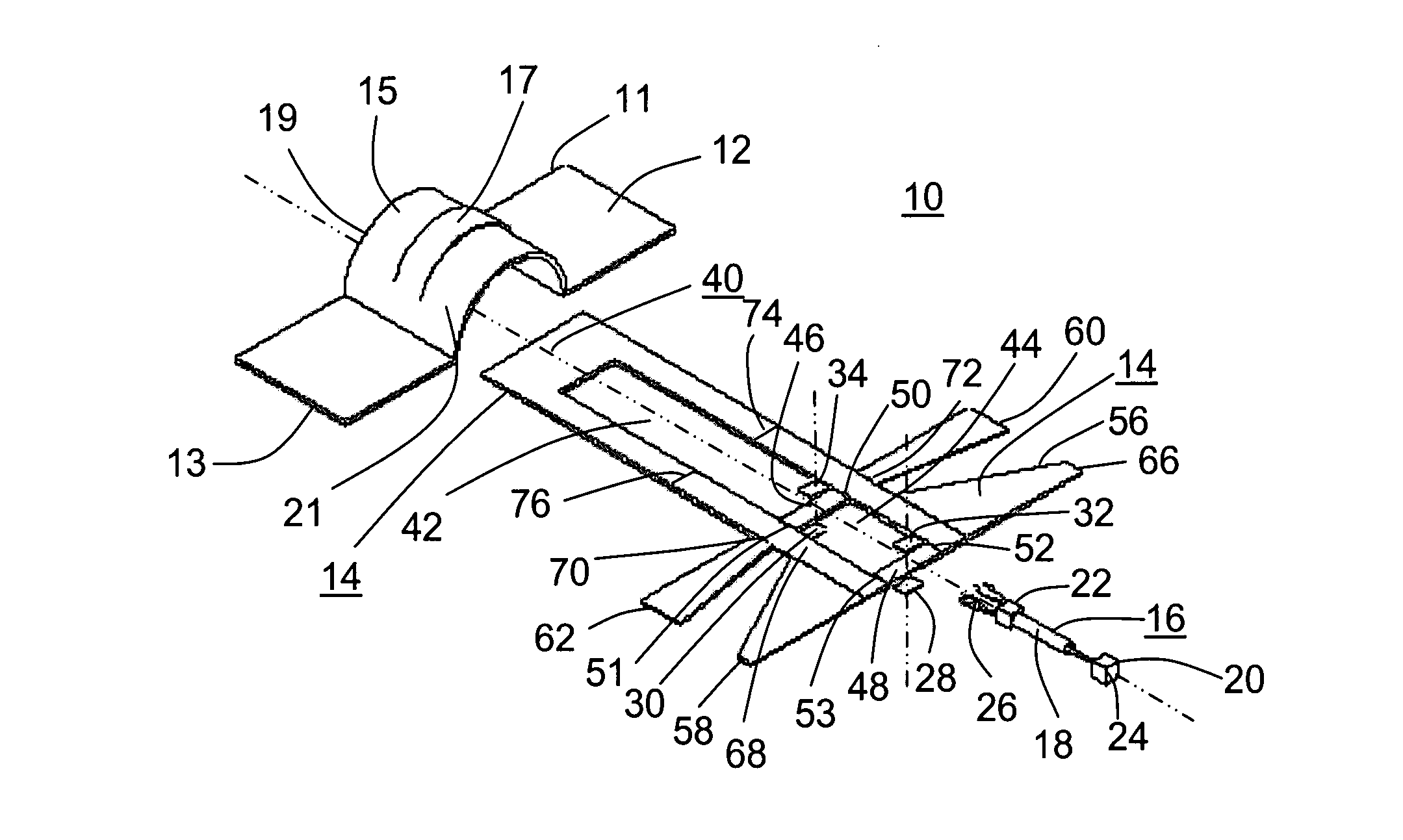
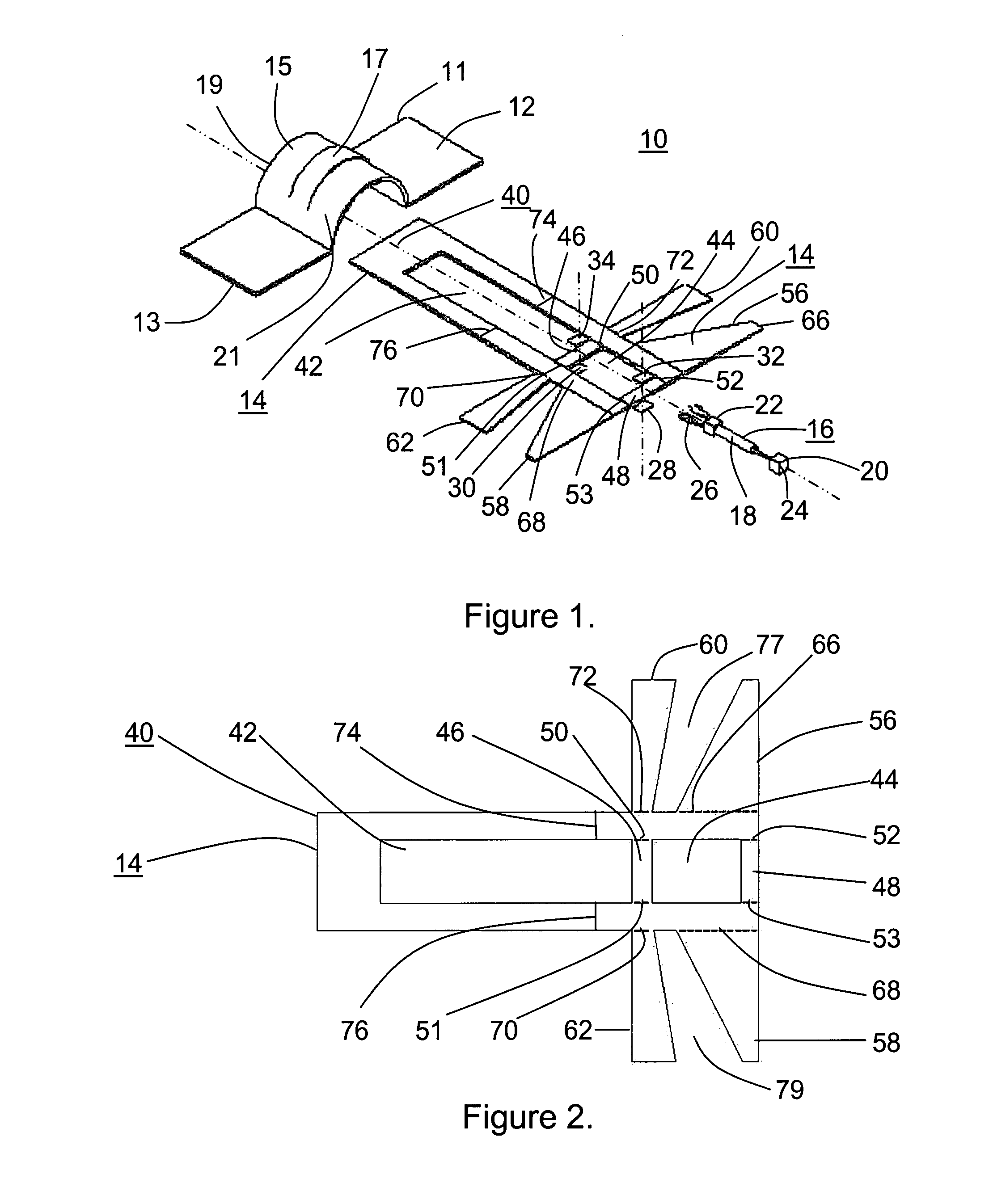
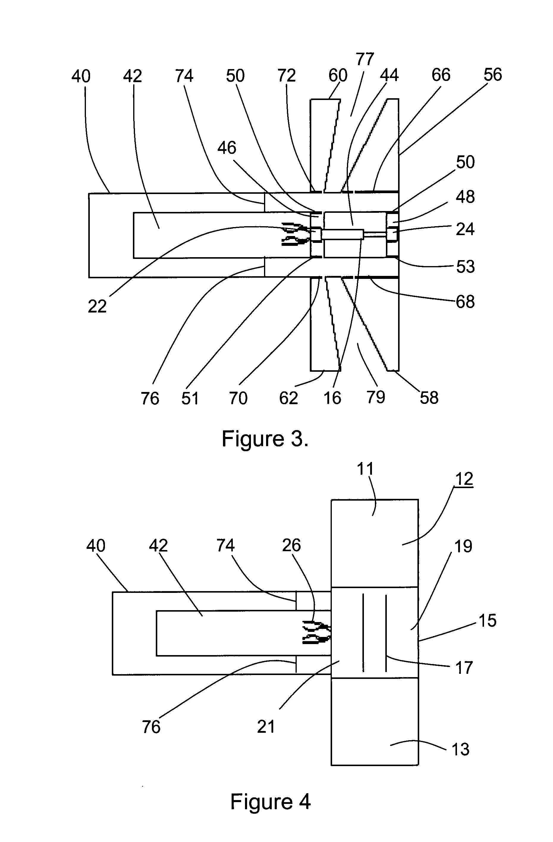
[0028]The bandage type sensor arrangement 10 of FIG. 1 includes a flexible bandage cover 12, a sensor carrier assembly 14 and a sensor 16 including two movable components 18 and 20 to provide indications of displacement there between. The bandage cover 12 includes an arched portion 15 having a stiffened portion 17 running along the center of the arched portion extending toward opposite ends of the bandage 11 and 13, and with flexible portions 19 and 21 on opposite sides of the stiffened portion 17. The stiffened portion 17 is formed by the application of an epoxy type cement. The bottom of the cover 12 with ends 11 and 13 include an adhesive for adhering the carrier assembly to a substrate to be tested.

[0029]The sensor 16 includes two mounts 22 and 24 attached to the components 18 and 20 respectively. Electrical connections to sensor coil portion 18 are provided by the wires 26 that may be tucked away under the bandage during installation so as to reduce stress on the sensor. Altern...


PUM


Abstract

A bandage type sensor arrangement wherein the sensor includes two parts movable with respect to each other, a carrier assembly is connected to the sensor parts for maintaining the sensor parts in place prior to use, and that is readily detachable for releasing the sensor parts while providing a connection of the sensor parts to a surface to be monitored. A cover is included as part of the carrier assembly to protect the operation of the sensor.

Description

FIELD OF THE INVENTION[0001]The present invention relates in general to pre-packaged sensors for monitoring movements in the form of deformations and displacements, and more particularly to sensor arrangements that can be readily attached to flexible membranes such as skin, and to carrier assemblies for the sensors.BACKGROUND OF THE INVENTION[0002]With the ever increasing growth of automated systems used in industrial and medical systems, there is the need for new, low cost and improved sensor apparatus or appliance and means for applying the sensors to substrates to detect movements thereof and for maintaining the sensors in place during tests. In the field of medicine there is continued research and development underway for measuring body internal and external physiological properties by non-intrusive means. This is particularly so as the sensors become miniaturized so as to be attached to the body and be worn with minimal discomfort, allowing the patient a significant amount of f...

Claims


Application Information

Patent Timeline
IPC IPC(8): G01L1/00
CPCA61B5/1126A61B2562/02G01D11/30G01D11/245G01B7/24
Inventor COCHRAN, WILLIAM T.
Owner MEDILITY
Why Eureka
Try Eureka