Stator of a rotary electric machine having stacked core teeth

a technology of electric machines and stacked teeth, which is applied in the direction of windings, dynamo-electric components, synchronous machines, etc., can solve the problems of winding falling out of the core slots, complex process and tooling required to apply varnish, and difficulty in inserting wires whose width fits closely, so as to reduce the reluctance of air gap, reduce the potential of winding falling out of the slots, and increase the surface area of the distal end

Inactive Publication Date: 2005-09-27
VISTEON GLOBAL TECH INC
View PDF112 Cites 14 Cited by
  • Summary
  • Abstract
  • Description
  • Claims
  • Application Information

AI Technical Summary

Benefits of technology

[0008]A cascaded winding increases the potential for the slot segment to fall out of a core slot compared to the interlaced winding because the cascaded winding has a slot segment housed in one core slot located at the innermost radial position, connected to an end loop segment which is located radially inward of all other end loop segments and which is connected to another slot segment housed in another core slot also located in the innermost radial position. Therefore, the slot segments housed in the core slots located at the innermost radial position and end loop segments that are connected to these slot segments are free to move radially inward and the slot segments can therefore potentially fall out of the core slots. In contrast, the interlaced winding has each slot segment housed in a core slot located in the innermost radial position connected to an end loop segment which bends outward to be located radially outward of other end loop segments and which is connected to a slot segment housed in another core slot located in the second innermost radial position. Therefore each slot segment located in the innermost radial position is connected to an end loop segment and another slot segment which are held outward by other end loop segments and other slot segments thereby minimizing the chance that the slot segment located at the innermost radial position will fall out of the slot.
[0011]The design of the stator assembly along with the process of radial insertion of the windings and staking of the core teeth in accordance with the present invention advantageously eliminates the potential of the winding falling out of the slots.
[0012]In a second aspect of the present invention. The distal ends of at least the majority of core teeth are staked along a substantial length of each core tooth so that they flare outwardly. In this way, the end of the core teeth are substantially widened, reducing the reluctance of the airgap between the rotor and stator by increasing the surface area of the distal ends of the core teeth. The increase in area of teeth provides a larger area for the flux to enter into the core teeth from the rotor pole finger face resulting in an increase in the machine's power density. In addition, the wider surface area of the core teeth effectively spreads out the flux field concentrated on the rotor pole surface, resulting in a lower variations in flux density on the pole surface. It is well known that the variation in flux density on the pole surface contributes to eddy current losses. Eddy currents are generated by changes in the flux density on a given surface resulting in variations in generated voltages at different points on the surface. Wider core teeth help to more evenly distribute the flux on the rotor pole finger, resulting in less eddy current loss. This reduction in losses reduces the heat generated by machine losses and improves the efficiency of the device.

Problems solved by technology

A disadvantage of the high slot fill stators is the difficulty of inserting the wires whose width fits closely to the width of the slots.
After the windings have been placed within the core slots, there is a possibility of the winding falling out of the core slots.
The process and tooling required to apply the varnish is complex and adds significant cost to the manufacturing of the core.
It is also known that there is a substantial amount of power loss on the surface of the pole fingers due to eddy currents passing through the steel causing heat.
Wider core teeth help to reduce the amount of flux density variation on the pole finger face and, therefore, result in lower power loss due to eddy currents.

Method used


Image

  • Stator of a rotary electric machine having stacked core teeth
  • Stator of a rotary electric machine having stacked core teeth
  • Stator of a rotary electric machine having stacked core teeth

Examples


first embodiment

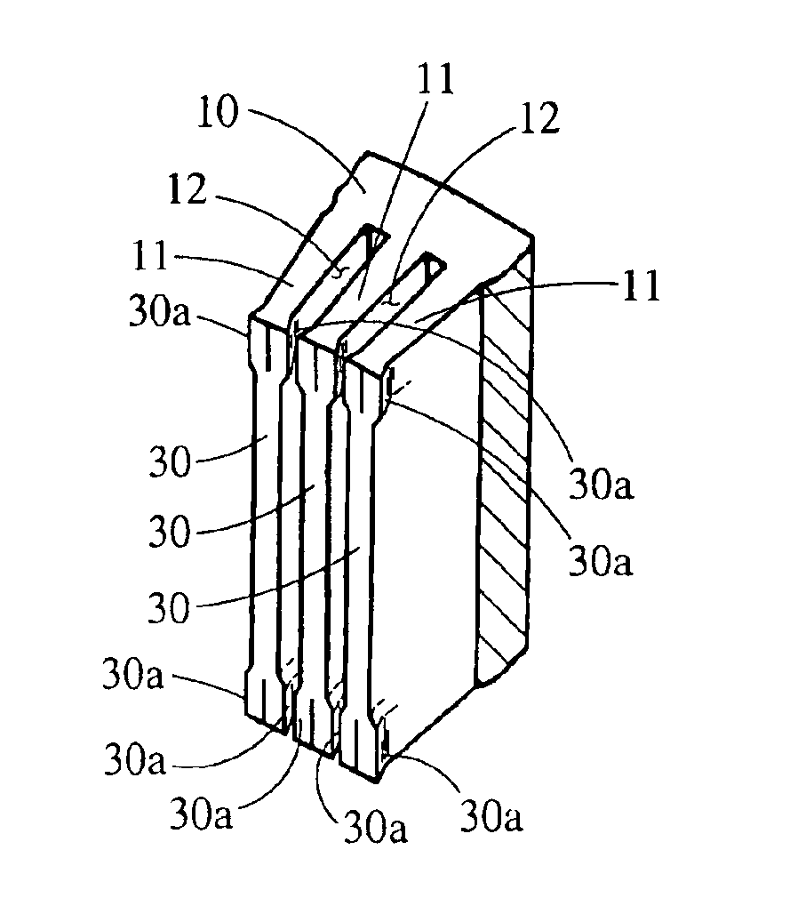
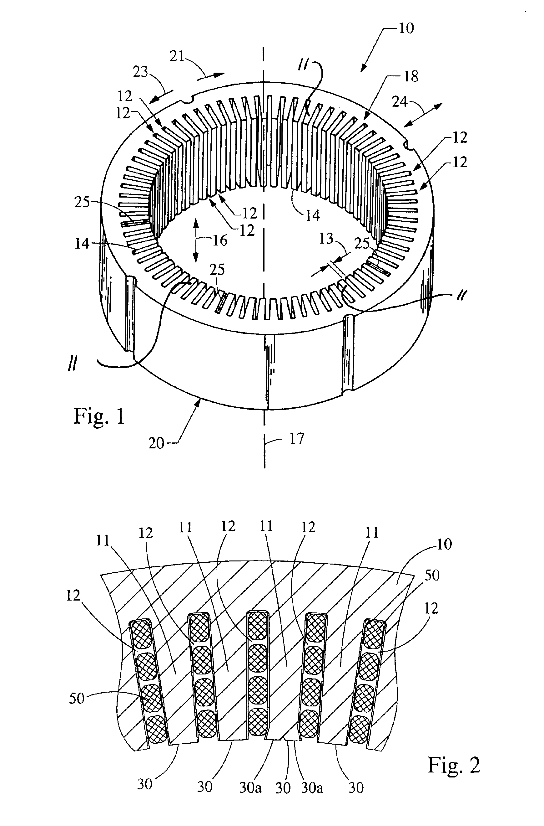
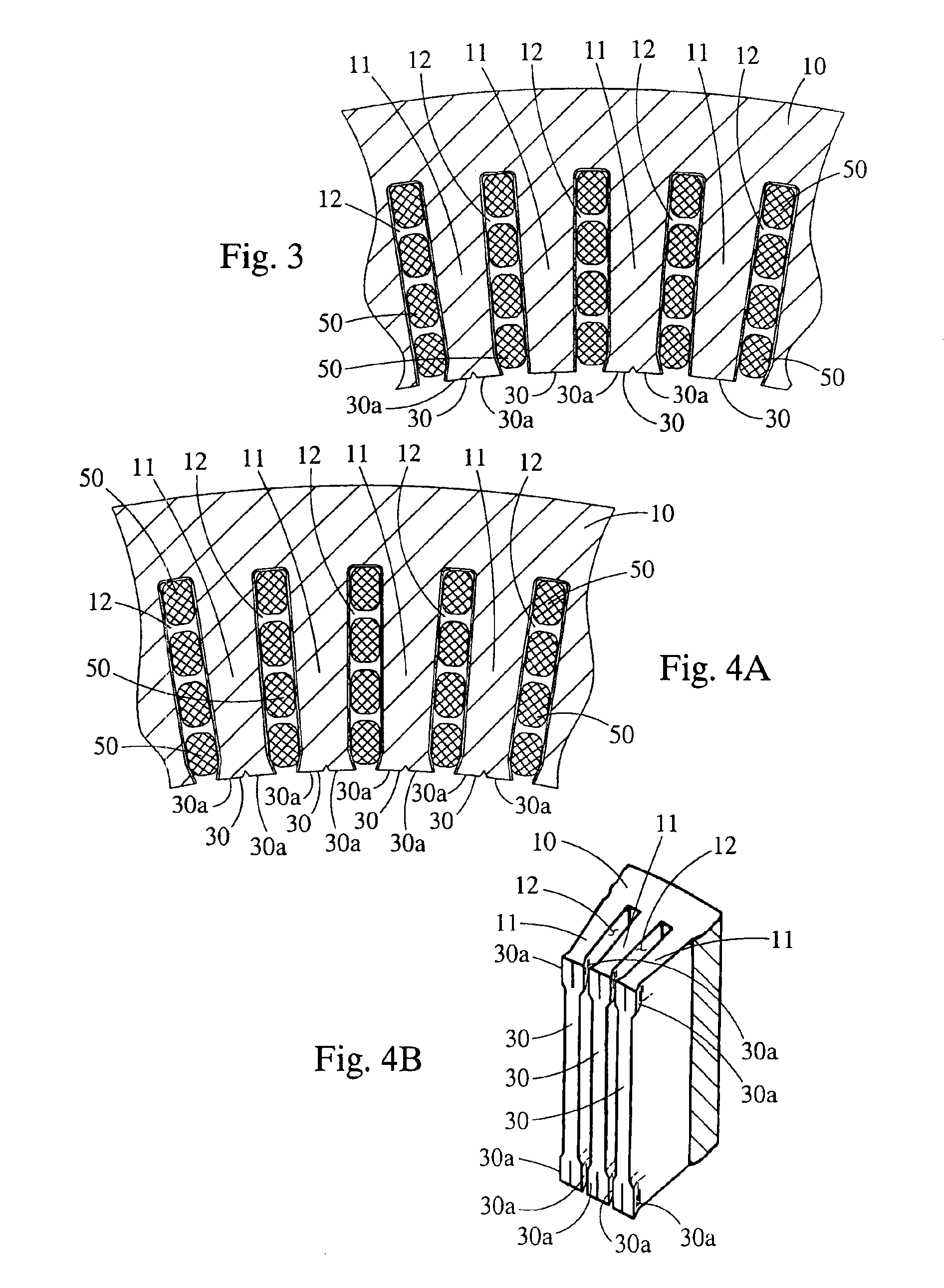
[0035]In the first embodiment, when forming the stator, the windings 50 are placed within the stator core 10 and tooling 32 is brought into contact with the distal end 30 of the core tooth 11 as shown in FIG. 5. Referring to FIG. 6, once the tooling 32 contacts the distal end 30 of the core tooth 11, additional force pushes the tooling 32 into the distal end 30 of the core tooth 11 forcing portions 30a of the distal end 30 of the core tooth 11 to flare outward. The flared portions 30a reduce the opening width of the core slot 12 to a size smaller than the width of the slot segments housed in the same core slot 12 such that the windings 50 cannot fall out of the core slots 12.

second embodiment

[0036]In the present invention, windings 50 are placed within that stator core 10 and tooling 32 that extends a substantial length of the stator core 10 is brought into contact with the ends of core teeth 11 as shown in FIG. 5. Referring to FIG. 6, once the tooling 32 contacts the end 30 of the core tooth 11, additional force pushes the tooling 32 into the distal end 30 of the core tooth 11 forcing portions 30a of the end 30 of the core tooth 11 to flare outward. The flared portions 30a reduce the opening width of the core slot 12 to a size smaller than the width of the slot segments housed in the same core slot 12 such that the windings 50 cannot fall out of the core slots 12.

[0037]As an alternative, the tooling 32 could be replaced with a roller-type tool 220 as shown in FIG. 9, that contains a plurality of protrusions 222. The roller-type tool 220 is inserted into the inside diameter of stator core 10 after the windings 50 are placed in the core slots 12. The roller-type tool 220...


PUM


Abstract

A stator of a rotary electric machine having secured core slot insulators includes a multi-phase stator winding, having a plurality of slot segments that are adapted to be radially inserted into a plurality of circumferentially spaced axially-extending core slots in a surface of a cylindrically-shaped stator core. The stator winding includes the plurality of slot segments alternately connected at the first and second ends of the stator core by a plurality of end loop segments to form the winding. At least one of the core teeth includes a distal end that is staked such that the distal end of the at least one core tooth is flared outward circumferentially to secure the stator winding within the core slots.

Description

CROSS REFERENCE TO RELATED APPLICATION[0001]The present application is a continuation-in-part application corresponding to U.S. patent application Ser. No. 10 / 899,338 filed on Jul. 26, 2004 entitled “Stator Winding Having Radial Aligned Wraps”, which is a continuation-in-part application corresponding to U.S. patent application Ser. No. 10 / 443,441 filed on May 22, 2003 entitled “Stator Winding Having Cascaded End Loops”, which corresponds to Provisional Patent Application Ser. No. 60 / 454,996, filed on Mar. 14, 2003. entitled “Stator Winding Having Cascade End Loops”.BACKGROUND OF THE INVENTION[0002]The present invention relates generally to electric machines and, in particular, to a stator for an electric machine having a core and a winding. Electric machines, such as alternating current electric generators, or alternators are well known. An automotive alternator is an electric machine which charges the battery of an automotive vehicle. Prior art automotive alternators typically inc...

Claims


Application Information

Patent Timeline
Patent Type & Authority Patents(United States)
IPC IPC(8): H02K3/50H02K15/00H02K3/493
CPCH02K3/493H02K15/0037
Inventor NEET, KIRK E.YORK, MICHAEL TIMOTHY
Owner VISTEON GLOBAL TECH INC
Why Eureka
Try Eureka