Valve with elbow joint diverter

a diverter valve and elbow joint technology, applied in the field of valves, can solve problems such as friction loss and turbulent flow, and achieve the effect of reducing pressure drop and turbulent flow

Inactive Publication Date: 2007-08-14
PENTAIR WATER POOL & SPA INC
View PDF41 Cites 20 Cited by
  • Summary
  • Abstract
  • Description
  • Claims
  • Application Information

AI Technical Summary

Benefits of technology

[0004]This invention provides a multiport diverter valve having a valving chamber therein. A plurality of ports open into the chamber and a flow diverter is pivotally mounted in the chamber. The flow diverter has a concave diverter surface forming a portion of a torus which could be a tubular portion. First and second ends of the torus with a first adjacent pair of the ports. This provides a smooth flow path between those ports to minimize pressure drop and turbulent flow. A handle connected to the flow diverter is adapted to pivot the diverter to a position connecting a second adjacent pair of ports. The second pair of ports includes one of the ports from the first pair. The flow diverter is adapted to pivot to a further position connecting all of the ports.

Problems solved by technology

Conventional diverter valves present a number of hydraulic engineering issues.
Also friction losses and turbulent flow is caused by the flow striking the flow diverter and being forced to turn 90° to the outlet port.

Method used


Image

  • Valve with elbow joint diverter
  • Valve with elbow joint diverter
  • Valve with elbow joint diverter

Examples


Embodiment Construction

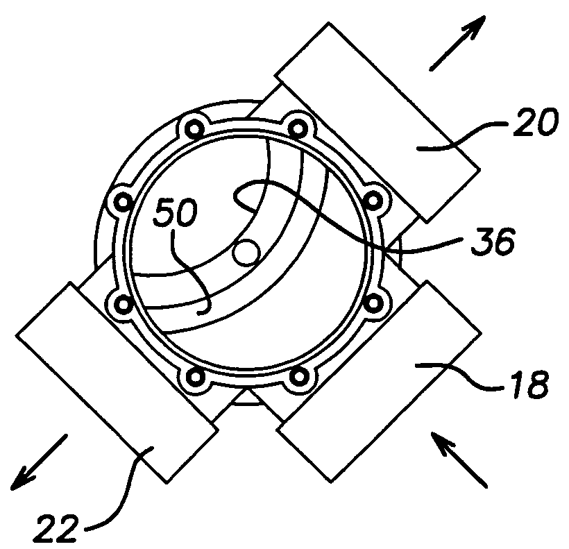
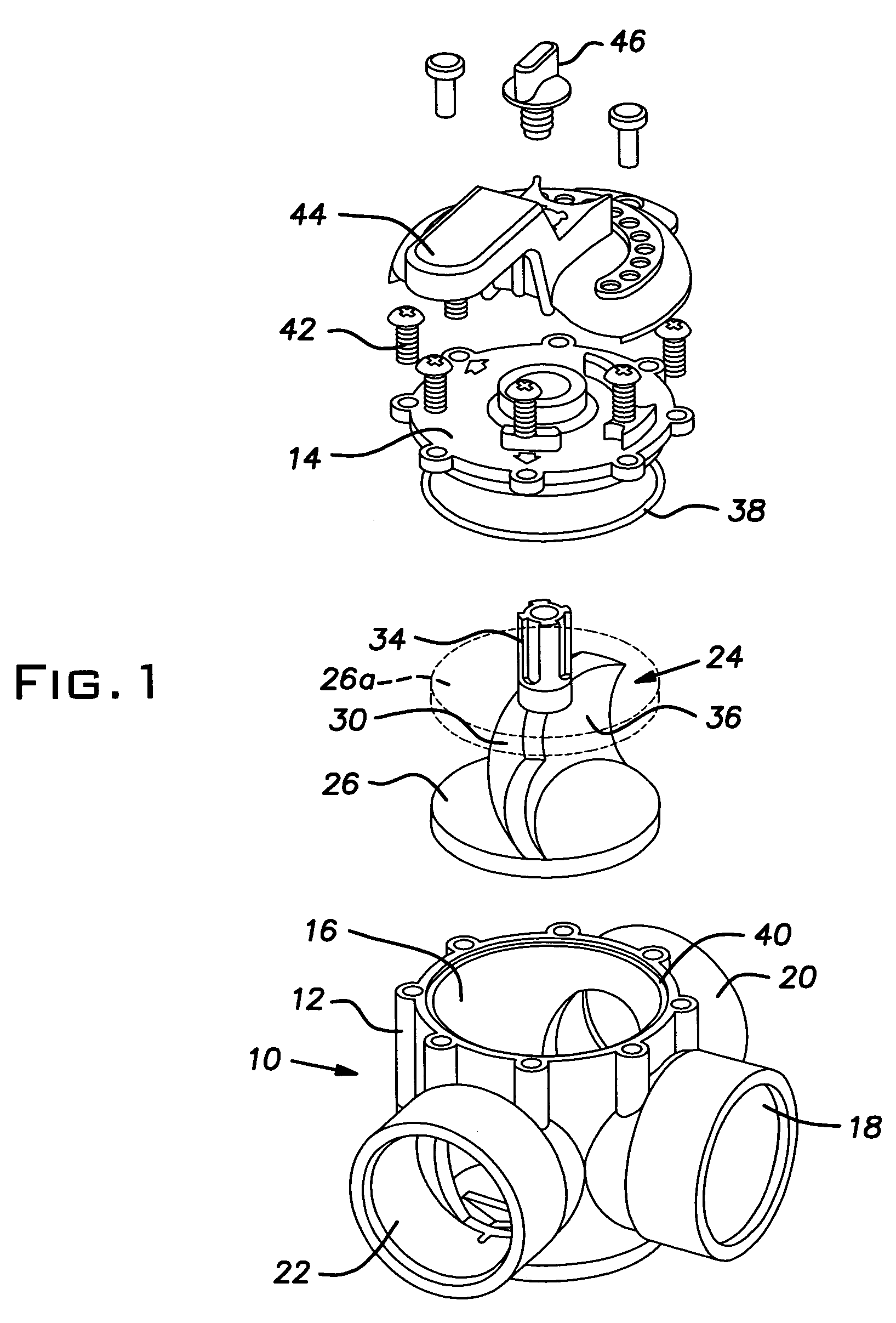
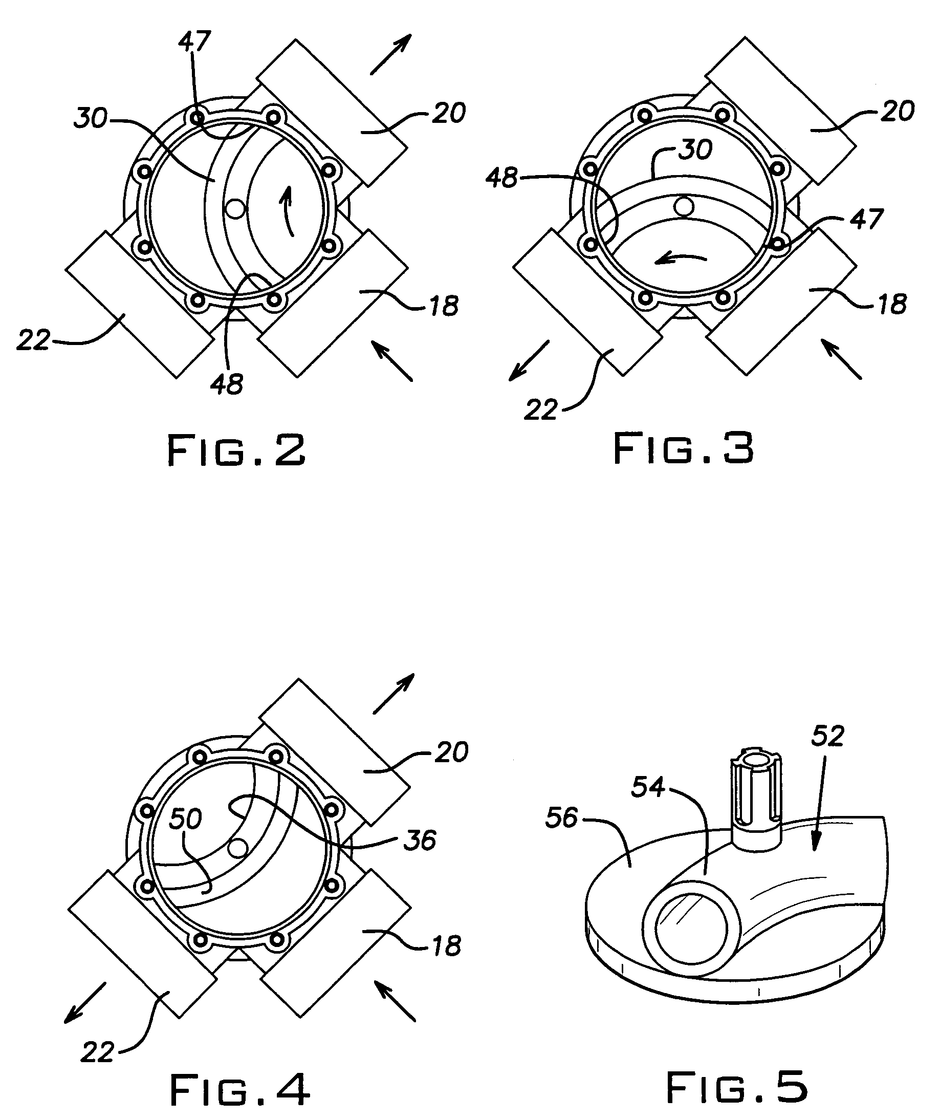
[0010]Referring now to the drawings and, particularly, to FIG. 1, there is illustrated a multiport diverter valve 10. The valve 10 includes a valve housing 12 which, with a cover 14, defines a valve chamber 16. A plurality of ports 18, 20, and 22 open into the chamber 16. A flow diverter 24 is pivotally mounted in the chamber 16. The flow diverter 24 includes a base plate 26 and a top plate 26(a) with an axially depending stub shaft (not shown) which is pivotally received in a socket (not shown) in the bottom of the chamber 16.

[0011]The flow diverter 24 also includes an elbow member 30 having a concave diverter surface 36 forming a portion of a torus. A mounting shaft 34 axially projects from the elbow member 30 and extends through the cover 14. An O-ring seal 38 is seated in a groove 40 in the upper rim of the valve housing 12 to seal the chamber 16. A plurality of screws 42 attach the cover 14 to the valve housing 12. A handle 44 is fixed to the shaft 34 by a screw 46. The mountin...


PUM


Abstract

A multiport diverter valve comprising a valve housing defining a valving chamber therein. A plurality of ports open into the chamber. A flow diverter is pivotally mounted in the chamber and has a concave diverter surface forming a portion of a torus. First and second ends of the torus communicate with a first adjacent pair of the ports to provide a flow path between the adjacent pair. A valve handle is adapted to pivot the diverter to a position connecting a second adjacent pair of the ports with the second pair of ports including one of the ports from the first pair. The handle is further adapted to pivot the diverter to a position connecting all of the ports.

Description

FIELD OF THE INVENTION[0001]This invention relates to valves and, more particularly to multiport diverter valves used to change the flow of water in pool / spa system. A diverter also allows the use of the spa and then may be switched to the pool. Typically it is a three port valve that closes off one port and allows water to be diverted in from another port through an alternate port.BACKGROUND OF THE INVENTION[0002]Conventional diverter valves present a number of hydraulic engineering issues. Fluid flowing into the valve chamber experiences a pressure drop due to the relatively large cross sectional area of the chamber compared to the inlet port. Also friction losses and turbulent flow is caused by the flow striking the flow diverter and being forced to turn 90° to the outlet port.[0003]Further, prior art diverter valves include flow diverters that close off a non-selected outlet port and permit flow to an open, selected port. The diversion occurs by default rather than a directional...

Claims


Application Information

Patent Timeline
Patent Type & Authority Patents(United States)
IPC IPC(8): F16K11/08
CPCF16K11/076F16K11/0853Y10T137/87804Y10T137/86871Y10T137/8782Y10T137/86863
Inventor LOPEZ, THOMAS P.
Owner PENTAIR WATER POOL & SPA INC
Why Eureka
Try Eureka