Compression tool jawset

a compression tool and jawset technology, applied in the field of compression tools, can solve the problems of reducing the stability of the pin in the opening, oversized crimps, and inability of the operator of the compression tool to operate,

Inactive Publication Date: 2007-08-28
EMERSON ELECTRIC CO
View PDF13 Cites 7 Cited by
  • Summary
  • Abstract
  • Description
  • Claims
  • Application Information

AI Technical Summary

Benefits of technology

[0031]While considerable emphasis has been placed herein on the structures and structural interrelationships between the component parts of the preferred embodiments, it will be appreciated that other embodiments can be made and that many changes can be made in the preferred embodiments without departing from the principles of the invention. In this respect, for example, the biasing spring can be hairpin shaped with the closed end thereof extending across the forward end of the spring pin. Further, if the fracture in a particular jaw arm design extends from the spring pin recess to a point forwardly or rearwardly of the pivot pin opening, it will be appreciated that the jaw arm will deform relative to the material between the end point of the fracture and the outer edge of the jaw arm, whereby modification of one or the other or both the pin opening and spring pin can be determined for achieving ejection of the spring pin or canting thereof in the spring pin opening to indicate a failure in accordance with the invention. Still further, it will be appreciated that jaw arms of compression tools of the character to which the invention is directed which do not have a spring pin and spring pin opening can be modified in this respect so as to enable designing the jaw arm for indicating a failure in accordance with the invention. Furthermore, a modified spring pin can be a modification of the original pin or can be manufactured with the modified profile. Accordingly, it is to be distinctly understood that the foregoing descriptive matter is to be interpreted merely as illustrative of the invention and not as a limitation and that it is intended to include other embodiments and all modifications of the preferred embodiments insofar as they come within the scope of the appended claims or the equivalents thereof.

Problems solved by technology

The occurrence of either of these events provides an immediate indication of failure to the operator of the compression tool.
The modification or modifications are based on an acceptable amount of relative deformation between the jawarms prior to a fracture reaching a point spaced outwardly from the pin opening and beyond which the deformation would be such as to cause unacceptable, oversized crimps to be made.
Upon a fracture and the ensuing deformation resulting in spreading of the pin recesses relative to one another, the stability of the pin in the opening is reduced and the spring biases the pin to a canted position in the opening and thus jams relative displacement of the jawarms in the direction to open the jaw recesses.

Method used


Image

  • Compression tool jawset
  • Compression tool jawset
  • Compression tool jawset

Examples


Embodiment Construction

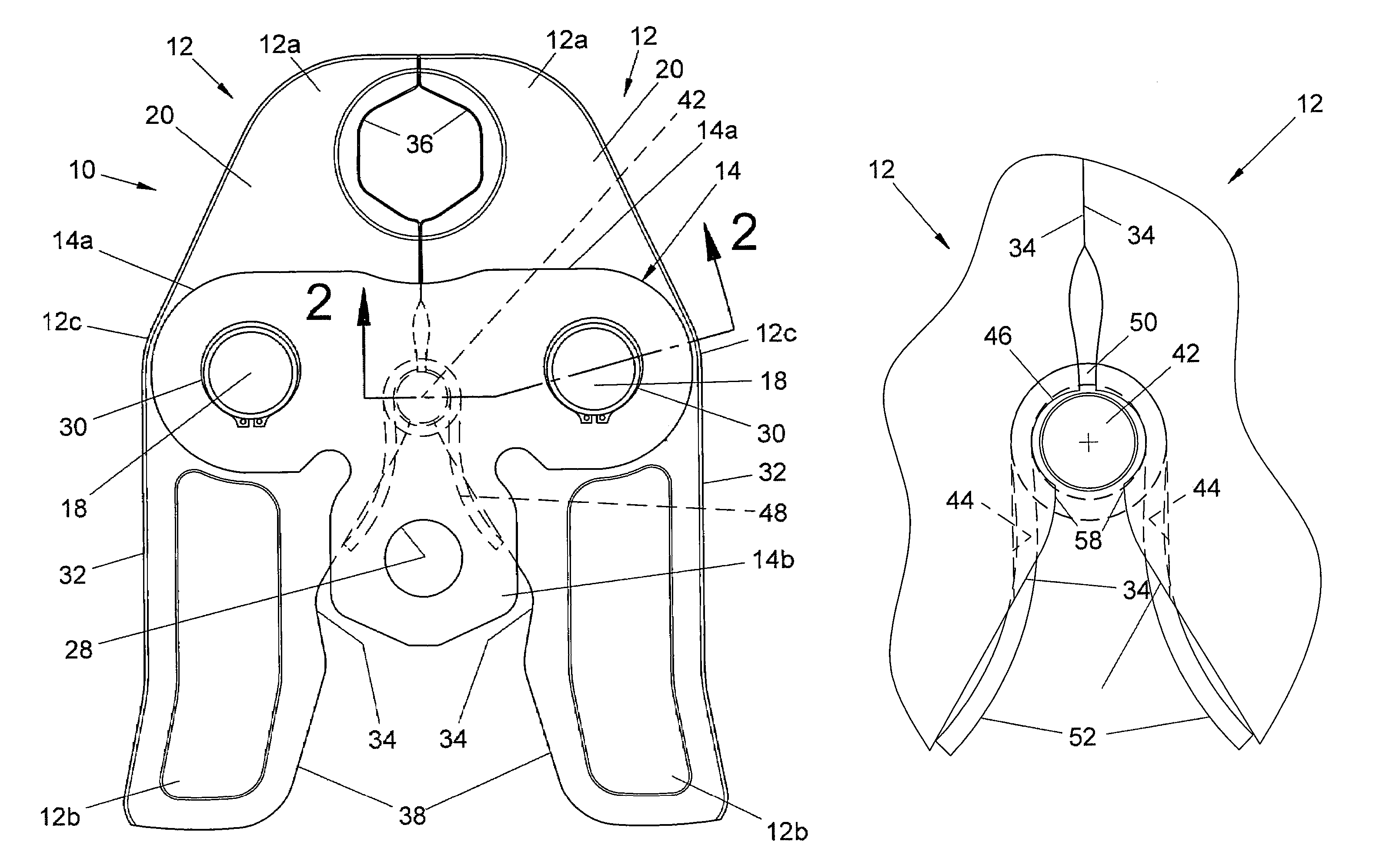
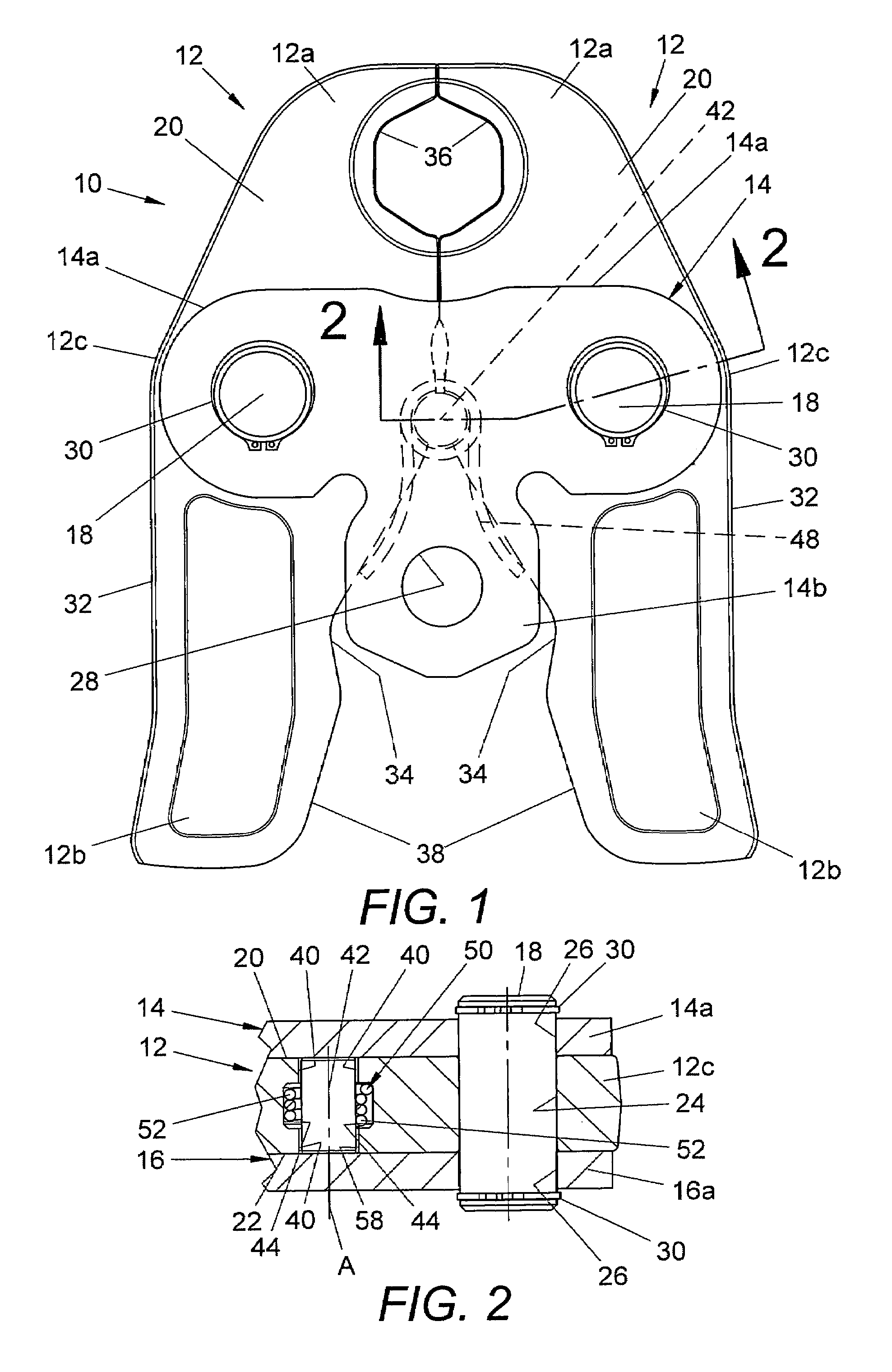
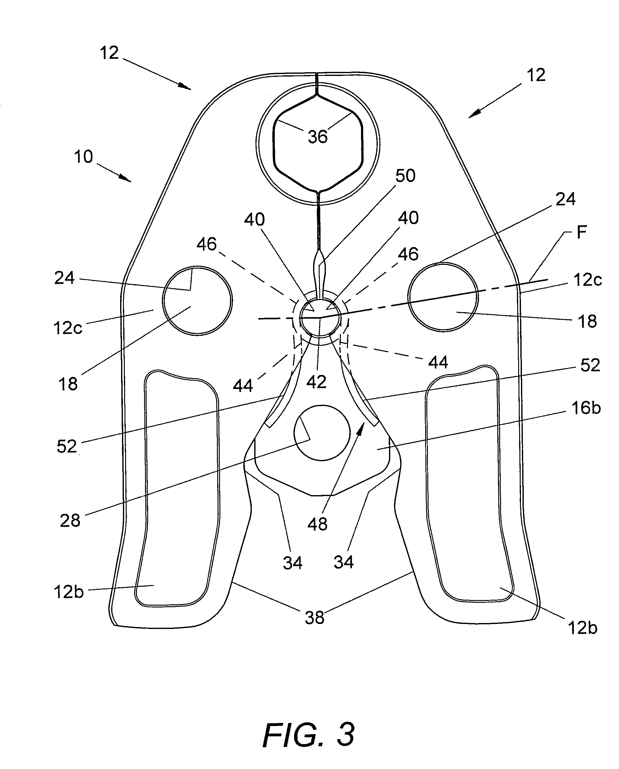
[0021]Referring now in greater detail to the drawings, wherein the showings are for the purpose of illustrating preferred embodiments of the invention only, and not for the purpose of limiting the invention, FIGS. 1-3 illustrate a jawset 10 comprising a pair of jawarm members 12 mounted, in the orientation shown in FIGS. 1 and 2, between top and bottom side plates 14 and 16, respectively, by a corresponding pivot pin 18. Each of the jawarm members 12 has a top side 20 and a bottom side 22 and a pivot pin opening 24 therethrough for receiving the corresponding pin 18. Side plates 14 and 16 are generally T-shaped and include laterally opposite sides 14a and 16a, respectively, which are provided with aligned holes 26 for receiving the outer ends of the corresponding pin 18. Side plates 14 and 16 further include rear ends 14b and 16b, respectively, which are provided with aligned openings 28 therethrough which are adapted to receive a mounting pin by which the jawset is mounted on a dri...


PUM


Abstract

A compression tool having a pair of jaw arms pivotal between side plates and having inner edges provided with laterally inwardly open opposed spring pin recesses providing an opening therebetween for a spring pin, and a spring associated with the pin and biasing the jaw arms in a closing direction and biasing the spring pin rearwardly of the spring pin opening has one or the other or both the spring pin opening and spring pin modified for the pin to be displaced from the spring pin opening or canted therein in response to a fracture of at least one of the jaw arms outwardly from the corresponding pin recess toward the outer edge of the jaw arm.

Description

BACKGROUND OF THE INVENTION[0001]This invention relates to the art of compression tools for joining pipes and couplings and, more particularly, to improvements by which a failure of one or both pivotal jawarm members of a compression jawset is indicated to a user thereof.[0002]A compression tool of the character to which the present invention relates is shown in U.S. Pat. No. 6,434,998 to Amherd. Such tools include a compression jawset removably mounted on a drive mechanism by which the jawarms of the set are displaced into compression about a pipe and coupling to join the latter. The jawset is comprised of a pair of jawarm members pivotally mounted between a pair of side plates and having laterally inwardly open opposed jaw recesses at one end and laterally inwardly facing cam surfaces at the opposite ends. The jawarms are pivotal about pins located in openings through the jawarms between the opposite ends thereof, and the jawarm members have laterally inner and outer edges between...

Claims


Application Information

Patent Timeline
Patent Type & Authority Patents(United States)
IPC IPC(8): B21D37/00B21D37/20
CPCB25B27/10
Inventor HAMM, JAMES E.WESTLEY, TODD A.
Owner EMERSON ELECTRIC CO
Why Eureka
Try Eureka